


Understanding and Specifying LIDT of Laser Components
This is Section 14.1 of the Laser Optics Resource Guide.
Laser-induced damage threshold (LIDT) is defined within ISO 21254 as the “highest quantity of laser radiation incident upon the optical component for which the extrapolated probability of damage is zero”.1 The purpose of LIDT is to specify the maximum laser fluence (for pulsed lasers, typically in J/cm2) or the maximum laser intensity (for continuous wave lasers, typically in W/cm2) that a laser optic can withstand before damage occurs. Because of the statistical nature of laser damage testing, LIDT cannot be considered as the fluence below which damage will never occur, but rather the fluence below which the damage probability is less than the critical risk level. The level of risk depends on several factors such as the beam diameter, the number of test sites per sample, and the number of samples tested in order to determine the specification.
Laser-induced damage in optical components causes degradation in system performance that can even result in catastrophic failure. An incorrect understanding of LIDT may lead to significantly higher costs or to component failures. Especially when dealing with high power lasers, LIDT is an important specification for all types of laser optics including reflective, transmissive, and absorptive components. The lack of an industry consensus on how LIDT should be tested, how damage should be detected, and how the test data should be interpreted makes LIDT a complicated specification. An LIDT value on its own does not convey the diameter of the beam used for testing, how many shots per testing site were administered, or the way the test data was analyzed.
Introduction to LIDT
In order to determine whether a laser’s fluence may cause damage to an optic, the following specifications of the laser should be reviewed: power, beam diameter, and whether the laser is continuous wave or pulsed. For pulsed lasers, the pulse duration must also be considered.
Laser Intensity: Not as Straightforward as it Seems
The intensity of a laser beam is the optical power per unit area, typically measured in W/cm2. The distribution of the intensity of the laser across a cross-section of the beam is the intensity profile. Some of the most common intensity profiles are flat top beams and Gaussian beams. Flat top beams, or top hat beams, have an intensity profile that is constant across a cross-section of the beam. Gaussian beams have an intensity profile that decreases as the distance from the center of the beam increases following a Gaussian function. The peak fluence of a Gaussian beam is twice as large as that of a flat top beam with the same optical power (Figure 1).
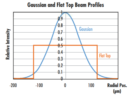
Figure 1: Comparison of Gaussian and flat top beam profiles with the same optical power2
The effective beam diameter of a Gaussian beam also scales with fluence. As fluence increases, a larger portion of the beam’s width has sufficient fluence to initiate laser-induced damage (Figure 2). This can be avoided by using a flat top beam instead of a Gaussian beam (see our Gaussian Beam Propagation and Why Use a Flat Top Laser Beam? application notes for more information).
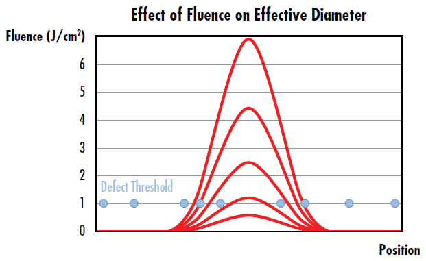
Figure 2: The effective diameter of a Gaussian beam increases as fluence increases, leading to a higher probability of laser-induced damage as indicated by more damage sites falling under the width of the curves with the highest fluence
The intensity of a laser plays an important role in determining the required LIDT for optics used with it. Some lasers also contain unintentional regions of higher intensity called hot spots, which can contribute to laser-induced damage.
Continuous Wave Lasers:
Damage from continuous wave (CW) lasers is typically a result of thermal effects caused by absorption in the optic’s coating or substrate.3 Cemented optical components, such as achromats, tend to have lower CW damage thresholds because of absorption or scattering in the cement.
To understand a CW LIDT specification, it is necessary to know the laser’s wavelength, beam diameter, power density, and intensity profile (e.g., Gaussian or flat top). LIDT for CW lasers is specified in units of power per area, typically in W/cm2. For example, if a 5mW, 532nm Nd:YAG laser with a flat top beam is used with a beam diameter of 1mm, then the power density is:
Therefore, if the LIDT specified for an optic is lower than 0.64W/cm2 then the user risks optical damage at 532nm. An extra factor of 2 would need to be added if using a Gaussian beam.
Pulsed Lasers:
Pulsed lasers emit discrete pulses of laser energy at a given repetition rate or frequency (Figure 3). The energy per pulse is directly proportional to the average power and inversely proportional to the repetition rate of the laser (Figure 4).
Damage from short nanosecond laser pulses is typically due to dielectric breakdown of the material resulting from exposure to the high electric fields in the laser beam.3 Dielectric breakdown occurs when a current flows through an electrical insulator because the applied voltage exceeds the material’s breakdown voltage. For longer pulse widths or high repetition rate laser systems, laser-induced damage may result from a combination of thermally induced damage and dielectric breakdown. This occurs because the pulse duration is still on the order of the time duration of electron-lattice dynamics, which is responsible for thermally induced damage. These thermal processes are negligible for ultrashort pulses of about 10ps or less.4 In this case, nonlinear excitation of electrons from the valence band to the conduction band, through mechanisms such as multiphoton absorption, multiphoton ionization, tunnel ionization, and avalanche ionization, leads to damage.5
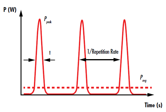
Figure 3: The pulses of a pulsed laser are temporally separated by the inverse of the repetition rate
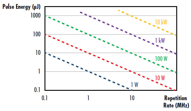
Figure 4: Depiction of the pulse energy as a function of repetition rate for a given average power of a pulsed laser
LIDT for pulsed lasers is specified as a fluence with units of J/cm2 as opposed to power density. It is important to recognize that while J/cm2 does not contain a unit of time, the damage threshold is dependent on pulse duration. In most cases, the LIDT fluence value will increase as the pulse duration increases. To understand a pulsed LIDT specification, it is necessary to know the laser’s wavelength, beam diameter, pulse energy, pulse duration, repetition rate, and intensity profile (e.g., Gaussian or flat top). The relationship between the fluence of a pulsed laser, the pulse energy, and the beam diameter is defined by:
For example, a flat top Q-switched (pulsed) laser with a pulse energy of 10mJ, pulse duration of 10ns, and a beam diameter of 10 microns will have the following fluence:
A fluence value in kilojoules is incredibly high and will almost certainly damage an optic, making factoring the beam diameter and not only laser energy in the calculations crucial.
Damage Mechanisms:
In addition to thermal buildup and dielectric breakdown, laser-induced damage can be triggered by the interaction of the laser with some type of defect. Defects include subsurface damage left behind from grinding and polishing processes, microscopic particles of polishing abrasive left on the optic, or clusters of metallic elements left behind from coating. Each of these defect sources exhibits distinct absorption characteristics, as the nature and size of any given defect determines the laser fluence the optic can withstand without causing damage.
As previously mentioned, pulse duration has a large impact on which mechanisms lead to laser-induced damage (Figure 5). Pulse durations on the order of femtoseconds to picoseconds may excite charge carriers from the valence band of a material to the conduction band, leading to nonlinear effects including multiphoton absorption, multiphoton ionization, tunnel ionization, and avalanche ionization (Table 1). Pulse durations on the order of picoseconds to nanoseconds may lead to damage by relaxing charge carriers from the conduction band back down to the valence band through carrier-carrier scattering and carrier-phonon scattering.
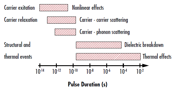
Figure 5: Temporal dependence of various laser-induced damage mechanisms6
| Damage Mechanism | Description |
|
Multiphoton Absorption |
Absorption process where two or more photons with energies lower than the material’s bandgap energy are absorbed simultaneously, making absorption no longer linearly proportional to intensity. |
| Multiphoton Ionization | Absorption of two or more photons whose combined energy leads to the photoionization of atoms in the material. |
| Tunnel Ionization | The strong electric field generated by ultra-short laser pulses allows electrons to “tunnel” through the potential barrier keeping the electrons bound to atoms, allowing them to escape. |
| Avalanche Ionization | The strong electric field generated by ultra-short laser pulses causes electrons to accelerate and collide with other atoms. This ionizes them and releases more electrons that continue to ionize other atoms. |
| Carrier-Carrier Scattering | Electrons accelerated by the electric field collide with other electrons, scattering them and causing them to collide with more electrons. |
| Carrier-Phonon Scattering | Electrons accelerated by the electric field excite phonons, or vibrations in the lattice of the material. |
| Dielectric Breakdown | A current flowing through an electrical insulator due to the applied voltage exceeding the material’s breakdown voltage. |
| Thermal Effects | Heat diffusion resulting from distortions and vibrations in the material caused by the energy of the laser pulses. |
Table 1: Descriptions of different damage mechanisms
Varying root causes of damage create different morphologies of laser-induced damage (Figure 6). Understanding these morphologies is important for coating and process development, but for laser optics applications, the morphology is only important in determining whether the damage significantly degrades the laser system’s performance. The amount of performance degradation a system can handle is application dependent. For example, in some situations a 10% reduction in transmission may be tolerable, while another system may fail if more than 1% of the incident light is scattered. According to the ISO 21254:2011 standard, any detectable change in an optic after exposure to a laser is considered damage.
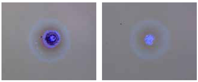
Figure 6: Various morphologies of laser-induced damage resulting from different root causes
Scaling LIDT:
It is important to keep in mind that damage threshold is dependent on wavelength and pulse duration. If the specified LIDT of an optic is at a different wavelength or pulse duration than that of the application, the LIDT must be evaluated at the application conditions. LIDT scaling should be avoided when possible; providing firm rules on scaling that are applicable in all situations is difficult, but general rules exist for scaling a LIDT value from the initial wavelength (λ1) and pulse duration (τ1) to a new wavelength (λ2) and pulse duration (τ2).7
This scaling should not be applied over large wavelength or pulse duration ranges. For example, Equation 5 would be adequate for a wavelength shift from 1064nm to 1030nm, but should not be applied for scaling an LIDT value at 1064nm to a drastically different wavelength, such as 355nm. Our Laser Induced Damage Threshold Scaling Calculator provides approximations for scaling an LIDT value for small shifts in application conditions.
References
- International Organization for Standardization. (2011). Lasers and laser-related equipment -- Test methods for laser-induced damage threshold -- Part 1: Definitions and general principles (ISO 21254-1:2011).
- R. M. Wood, Optics and Laser Tech. 29, 517, 1998.
- Paschotta, Rüdiger. Encyclopedia of Laser Physics and Technology, RP Photonics, October 2017, www.rp-photonics.com/encyclopedia.html.
- R. M. Wood, Optics and Laser Tech. 29, 517, 1998.
- Jing, X. et al., “Calculation of Femtosecond Pulse Laser-Induced Damage Threshold for Broadband Antireflective Microstructure Arrays.” Opt. Exp. 2009, 17, 24137.
- Mao, S. S. et al., “Dynamics of Femtosecond Laser Interactions with Dielectrics.” Appl. Phys. A 2004, 79, 1695.
- Mazur, Eric, and Rafael R Gattass. “Femtosecond Laser Micromachining in Transparent Materials.” Nature Photonics, vol. 2, 2008, pp. 219–225.
- Carr, C. W., et al. “Wavelength Dependence of Laser-Induced Damage: Determining the Damage Initiation Mechanisms.” Physical Review Letters, 91, 12, 2003.
More Resources
- Laser Damage Threshold Testing Application Note
- Laser Damage Threshold Scaling Calculator
- Uncertainty in LIDT Specifications Application Note
- Different Types of LIDT Specifications Application Note
- Bulk Laser Damage in Glass Application Note
- Importance of Beam Diameter on Laser Damage Threshold Application Note
- LIDT for Ultrafast Lasers Application Note
- Why Laser Damage Testing is Critical for UV Laser Applications Application Note
- A Guide to (Not Over) Specifying Losses in Laser Optics Application Note
- Metrology at Edmund Optics: Measuring as a Key Component of Manufacturing Video
- Metrology for Laser Optics Application Note
- Key Parameters of a Laser System Application Note
- Laser Optics Lab Video Series


or view regional numbers
QUOTE TOOL
enter stock numbers to begin
Copyright 2024, Edmund Optics Singapore Pte. Ltd, 18 Woodlands Loop #04-00, Singapore 738100
California Consumer Privacy Acts (CCPA): Do Not Sell or Share My Personal Information
California Transparency in Supply Chains Act
This content may include material that has been generated or modified using artificial intelligence (AI).
The FUTURE Depends On Optics®