


Relative Illumination, Roll-Off, and Vignetting
This is Section 3.2 of the Imaging Resource Guide.
To troubleshoot issues associated with relative illumination (RI), roll-off, and vignetting (the blocking of rays that pass through the outer edges of an imaging lens), sensor formats must be considered. More information on sensors and formats can be found in Sensors.
Matching Sensors with Lenses
One issue that often arises is the ability of an imaging lens to support certain sensor sizes. If a sensor is too large for the lens design, the image may appear to degrade or fade towards the edges; this effect is caused by vignetting. As resolution demands increase, one of two things must happen: pixel size must decrease, or sensor size must increase. Explained in The Airy Disk and Diffraction Limit and The Modulation Transfer Function (MTF) on the diffraction limit and MTF, continuous reduction in pixel size creates issues with the optics’ ability to resolve true detail. This concern, along with an increased signal-to-noise ratio, and the sensitivity issues associated with current sensor technology, results in sensor sizes increasing. Such size increase causes issues regarding vignetting and roll-off, unless the proper lens is used.
Relative Illumination

Figure 1: A set of RI curves showing relevant image sensor formats on the x-axis.
Figure 1 shows a typical RI curve, with the image height vs relative brightness. The individual curves represent RI performance at different f/#s. Note that RI is not absolute brightness; higher f/#s will still cause overall brightness to decrease, (learn more about f/# in System Throughput, f/#, and Numerical Aperture). The x-axis represents the distance from the center of the sensor to the corner of the sensor. The y-axis indicates how much illumination is at any position in the field relative to the point of highest illumination (typically the center of the field) which is set as 100% RI. To specify a lens's RI performance across different sensors, dotted vertical lines for sensor diagonals are superimposed. Figure 2 is an image projection of the RI in Figure 1 at f/1.4.

Figure 2: This image shows how the f/1.4 blue curve will appear across a 2/3” sensor.
The curve in Figure 1 shows that at its lowest f/#, f/1.4 (the blue line), this lens has an RI of 57% of the illumination level of the image center at the corner of a 2/3” sensor. Under the same conditions, the lens has an RI of 72% in the corner of a 1/2” sensor. As the sensor gets smaller, RI improves. Note that the RI improves as the f/# is increased; this occurs until there is no more vignetting in the lens, at which point all higher f/# settings will have the same illumination profile. Increasing the f/# does not increase the image circle size much; a lens designed for a particular sensor size will not perform well on a larger sensor, even with the f/# stopped down.
Roll-off will still occur when the lens is stopped down, as that is related to the angle of the rays and not the number of rays that pass through the lens. Many lenses will have an illumination profile that is highest in the center of the field and is either flat or declines to some lower percentage as it approaches the edge. There are rare cases where the RI increases slightly across the image circle; this is related to pupil compression and will not be covered in this text.
Vignetting Within the Lens - ADVANCED
Vignetting occurs when light rays do not make it through the entire lens system to the sensor, due to being blocked by the edges of individual lens elements or mechanical stops. This clipping of rays can be intentional or unintentional, and in some case is unavoidable. Vignetting is most often seen at or in lower f/#s, short focal length lenses, or lenses where higher resolutions need to be achieved at a lower cost.
Figure 3 demonstrates clipping as it may occur for the same 16mm lens at different f/#s (f/1.8 and f/4). Note the clipping of rays in Figure 3a, as indicated with red circles; these rays are not able to pass through the all the optics in the lens. Figure 3b, on the other hand, demonstrates an example without vignetting. The vignetting in Figure 3a could have several causes, including diameter limitations of the optics or a need to eliminate the rays to block stray light. Vignetting is sometimes purposely included in a lens design to improve overall lens performance or reduce cost.


Figure 3: A 16mm lens design at f/1.8 (a) and f/4 (b). At f/1.8 vignetting occurs where light rays are clipped by the edges of the lens.
Selective Vignetting to Gain Performance - ADVANCED
Vignetting is often used to maximize the resolution of a lens design across the entire image circle. Since it is more difficult to direct the rays that create the edge of an image to the desired location on a sensor, higher resolution objects are generally more difficult to reproduce at the edge of the image than at the center. Rays that end up on the wrong pixel will degrade the image at that location; one way to manage this is to eliminate these rays from the system. If the undesired rays do not make it to the sensor, they cannot degrade the image. Removing these mis-directed rays, however, reduces relative illumination.
Vignetting at the Pixel Level: Large vs. Small Pixels
Figure 4 illustrates light rays incident on a pixel in the corner and center of a sensor at f/1.4 (a and b) and f/2.8 (c and d). In Figure 4a, some light spills onto the adjacent pixel creating slight image and contrast degradation. Increasing the f/# (Figure 4c) essentially creates vignetting which clips those extraneous rays and improves image contrast. Figure 5 illustrates this same vignetting effect with smaller pixels. However, with the larger pixels in Figure 4, the change in f/# has much less of an effect on the overall image quality, because it occurs over a smaller number of pixels.

Figure 4: Light rays incident pixels in the corner of a sensor at f/1.4 (a and b), and f/2.8 (c and d). Increasing the f/# creates vignetting which clips the extraneous rays spilling onto the adjacent pixel in (a) and improves contrast.
In Figure 5, the pixels have been reduced to half the size, yielding a 4X resolution increase. In this example, vignetting by increasing f/# greatly, improves performance across the entire sensor, as opposed to the first example which only slightly improved the imaging performance in the corner of the image.

Figure 5: Light rays incident on pixels in the center of a sensor at f/1.4 (a and b), and f/2.8 (c and d). For large pixels, increasing the f/# has a less significant effect on image quality as all rays were nearly contained in the desired pixel. For small pixels, increasing the f/# creates vignetting which prevents the extraneous rays from spilling onto nearby pixels.
Figures 4 and 5 exhibit nominal design capabilities and do not account for reduced performance that results from manufacturing tolerances. With tolerances included, the need for vignetting can be even more pronounced, especially in cases where cost is a driving factor.
Vignetting can also be purposefully designed into lenses in scenarios in which the effects from manufacturing tolerances adversely affect the control of rays, causing image degradation. The looser the tolerances on the lens, the more adverse these degrading effects can become, and tightening the tolerances is often not practical due to the increase in manufacturing cost. Often, a balance must be struck between reducing manufacturing cost and maintaining image quality. In cases where cost is a primary factor, vignetting must be utilized in an attempt maintain resolution across the field of view. Doing such will have an adverse effect on the illumination profile. Designing vignetting into a lens can be accomplished in a couple different ways: by purposefully designing the clear apertures of the individual lens elements such that they vignette severely off-axis rays, or by introducing mechanical apertures to block aberrated rays, as shown in Figure 8a.
Vignetting in Different Lens Designs - ADVANCED
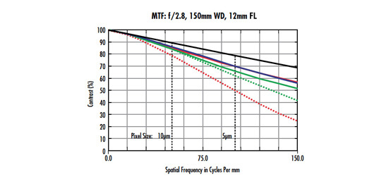
Figure 6 features a standard 12mm Lens design layout, along with both its relative illumination and MTF curves. Note the size difference of the ray bundles in 6a at the center (blue lines) and corner (green lines); the size difference demonstrates a large amount of selective vignetting. The vignetting leads to lower illumination at the edges of the image than in the center (6b). This is done to minimize the costs associated with materials and manufacturing tolerances, while maintaining reasonable performance at a lower price.


Figure 6: A standard 12mm lens ray path (a), relative illumination curve (b), and MTF curve (c).
The lens in Figure 7, an ultra-high resolution 12mm lens design, has a much more evenly sized ray bundles across the field (7a) due to a low level of vignetting. This translates to much more even relative illumination across the entire sensor (7b). The lens in this example is designed using more costly materials at tighter tolerances, which allows it to maintain high levels of performance across the image, without the need to introduce vignetting to improve its performance. The trade off in using such a lens is that the ultra-high-resolution lens is more expensive than the standard design.


Figure 7: An ultra-high-resolution 12mm lens ray path (a), relative illumination curve (b), and MTF curve (c).
Illumination Roll-Off - ADVANCED
Roll-off is the decrease in RI with respect to field, not caused by vignetting, but by radiometric laws, Figure 8. In its simplest form, the maximum brightness of an image circle produced by a lens with no vignetting is limited by the fourth power of the cosine of the chief ray angle in image space. This is known as cos4θ roll-off (most often referred to as “cosine to the fourth” roll-off).
Figure 8: Roll-off is the decrease in relative illumination with respect to field that is not caused by vignetting, but by radiometric laws.
Figure 9 shows the chief rays for the center and the corner of the image (highlighted in red). In many applications, roll-off is not an issue, but it can be a problem when the chief ray angle becomes steep. This is especially valid for applications using large or line-scan sensors, and applications with wide angular FOVs (short focal length).

Figure 9: An imaging lens layout highlighting the chief rays of the ray bundles belonging to the center (blue) and corner (green) of the image. These define the angle which is used to approximate roll-off.
Table 1 shows how roll-off increases with the chief ray angle. Note for an angle of 15°, there is a decrease in RI of about 13% from the center to the corner, but by doubling the angle, the roll-off increases to nearly a 44% reduction of RI. Roll-off must be considered in applications with short WDs and large FOVs. These types of lenses generally have large chief ray angles in image space, regardless of sensor size.
| Chief Ray Angle | Maximum Relative Illumination Level Center to Corner |
|---|---|
| 5° | 98.5% |
| 10° | 94.0% |
| 15° | 87.1% |
| 30° | 56.3% |
| 45° | 25.0% |
| 60° | 6.3% |
Table 1: The relation between chief ray angle and RI at the corner of an image, assuming 100% RI at the center.
One way to correct for roll-off is by designing the lens to be image space telecentric. By doing this, the difference in the angle of the chief rays will be 0°, which produces even illumination. Another way to offset roll-off is to create unbalanced illumination on the object under inspection. By mounting additional lights closer to the edges of the object under inspection or by adding an apodizing neutral density (ND) filter onto the lens, roll-off can be reduced.
Roll-Off and Micro Lenses - ADVANCED
Micro lenses are utilized on many sensors in an eff ort to increase the amount of light making it to the active pixel area. Like all other lenses, micro lenses have an angular acceptance in which they operate most efficiency. As the angle of incidence increases, the amount of light that makes it to the active area of the pixel is reduced. Most lens designs attempt to keep their image space chief ray angles below 5 to 7° in order to reduce these effects. Figure 10a shows a micro lens over the pixel.


Figure 10: Angle of incidence of the chief ray affects roll-off and relative illumination.
Figures 10b and 10c show how light is focused at normal incidence and at an oblique incidence to the micro lens, respectively. Normal incidence would represent the center pixel on the sensor. At this position all rays are focused onto the active area of the pixel. At oblique angles, not all rays make it to the active pixel area. This results in additional reduced RI beyond what is specified in a lens’s RI curve.


or view regional numbers
QUOTE TOOL
enter stock numbers to begin
Copyright 2024, Edmund Optics Singapore Pte. Ltd, 18 Woodlands Loop #04-00, Singapore 738100
California Consumer Privacy Acts (CCPA): Do Not Sell or Share My Personal Information
California Transparency in Supply Chains Act
This content may include material that has been generated or modified using artificial intelligence (AI).
The FUTURE Depends On Optics®