Building a Mach-Zehnder Interferometerhttp://www.edmundoptics.com.sg/knowledge-center/application-notes/optomechanics/building-a-mach-zehnder-interferometer/
http://www.edmundoptics.com.sg
Building a Mach-Zehnder Interferometer
What is a Mach-Zehnder Interferometer?
Mach-Zehnder interferometers are simple interferometric instruments that measure the relative phase shift between two collimated light beams. This phase shift can be used to determine small displacements, the transmitted wavefront error of transmissive optics, the refractive index of transparent materials, air flow in wind tunnels, and more.
Mach-Zehnder interferometers consist of a coherent light source like a laser, two beamsplitters, and two mirrors (Figure 1 and Figure 2). First, the light source is split into two paths using the first beamsplitter. The two beams each have the same optical path length, which is the distance traveled multiplied by the refractive index of the media they travel through. Each beam reflects off of a mirror and is recombined by the second beamsplitter. If there is a difference in the optical path lengths of the two beams that is less than the coherence length of the light source, interference fringes will be generated. Because the coherence length of a source can be extremely short, precision components and alignment are crucial. A sample can be measured by being placed in one of the beam paths. The resulting optical path length difference can be measured by observing the change in the interference fringes.
Figure 1: Typical optical schematic of a Mach-Zehnder interferometer Figure 2: Assembled tabletop Mach-Zehnder interferometer system constructed out of off-the-shelf components from Edmund Optics®
Assembling System using Off-the-Shelf Components from Edmund Optics®
A system like the one shown in Figure 2 can be assembled by following the guide below.
Sub-Assemblies
Each optical sub-assembly can be added to a table-top breadboard and easily slid along the optical axis via optical rails. The small linear motion stage placed on the carrier of the optical rail makes it easy to make fine adjustments in the optical axis direction or the orthogonal direction.
25mm Diameter 50R/50T, VIS Wedged Plate Beamsplitter
2
Aligning a Mach-Zehnder Interferometer
The laser, iris, and lenses must be aligned to the same optical axis. Ideally, the optical axis of these components should not change even if they are translated on the optical rail. A stage installed on the optical rail carrier allows for horizontal movement perpendicular to the direction of the rail.
Installing the Laser Module
Fix the laser module (diameter Φ19.1mm) to #15866 using the adapter (#18291).
This makes it easy to adjust the laser angle.
Adjust the angle of the mount so that the laser beam is parallel to the optical rail.
Figure 10: Installing the laser module
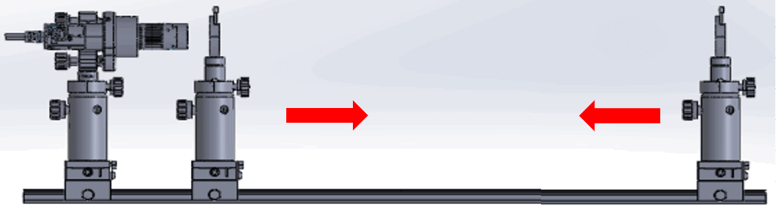
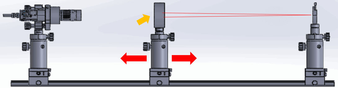
Aligning the Laser's Optical Axis
Use the iris sub-assembly to keep the center of the optical axis of all components of the system constant.
Direct the laser onto the center of the iris.
Slide the iris down the optical rail while making adjustments to the kinematic mount to keep the laser centered on the iris throughout the whole range.
Figure 11: Aligning the laser's optical axis
Aligning the Plano-Convex Lens' Optical Axis
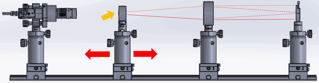
Adjust the optical axis of a plano-convex lens with the long focal length while sliding the lens unit left and right.
Use the post to adjust the height of the lens and use the dovetail stage to adjust the optical axis in the perpendicular direction.
Figure 12: Aligning the optical axis of the plano-convex lens with the long focal length
Aligning the Plano-Concave Lens' Optical Axis
Place a plano-concave lens with a short focal length in the optical path.
Adjust the optical axis while sliding the lens unit left and right.
Use the post to adjust the height of the lens and use the dovetail stage to adjust the optical axis in the perpendicular direction.
Figure 13: Aligning the optical axis of the plano-concave lens with the short focal length
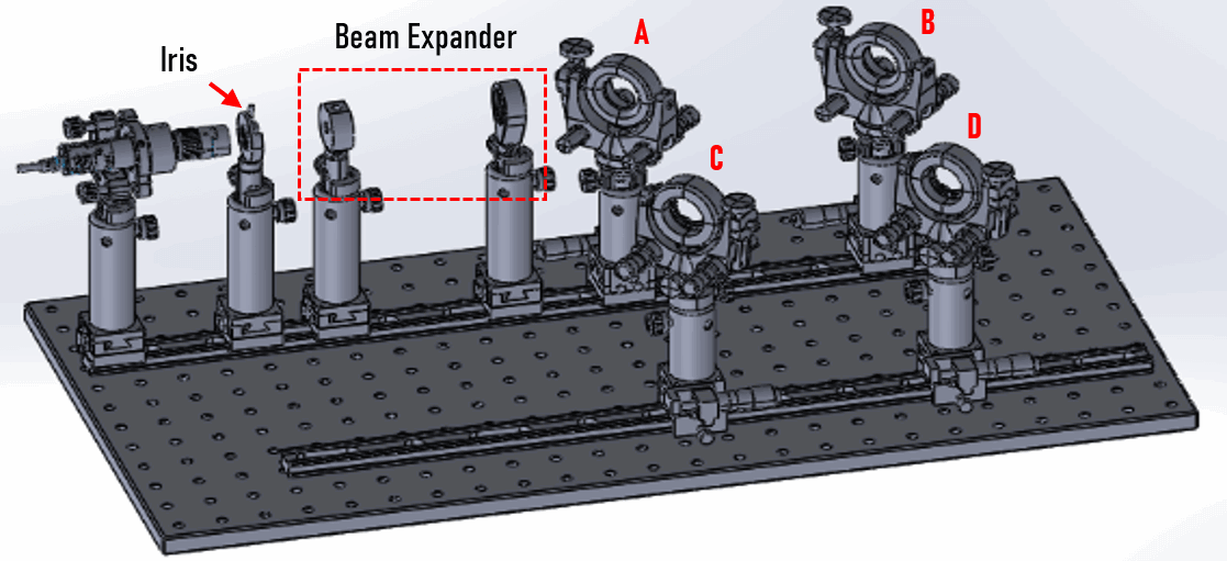
Positioning Lenses to Form Beam Expander
The two lenses should be separated by the sum of their focal lengths. In this case, the separation should be 76.2mm – 25mm = 51.2mm.
Please select your shipping country to view the most accurate inventory information, and to determine the correct Edmund Optics sales office for your order.


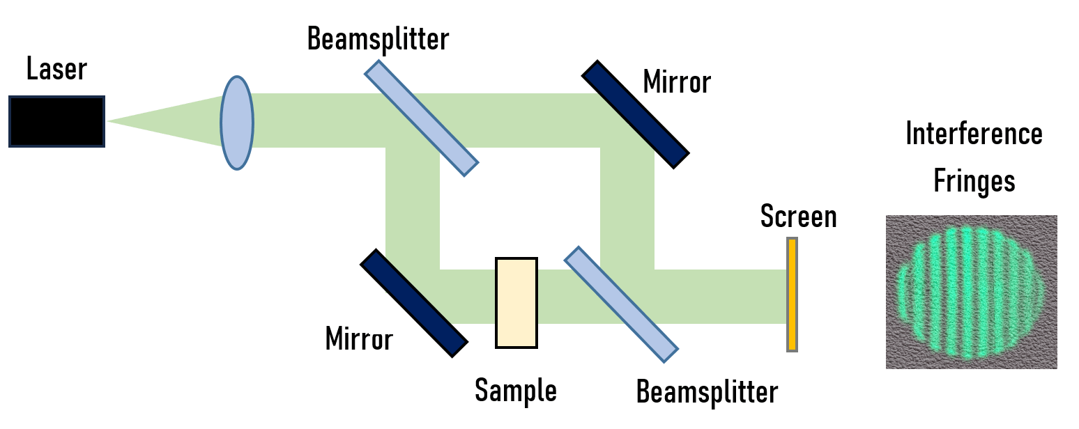
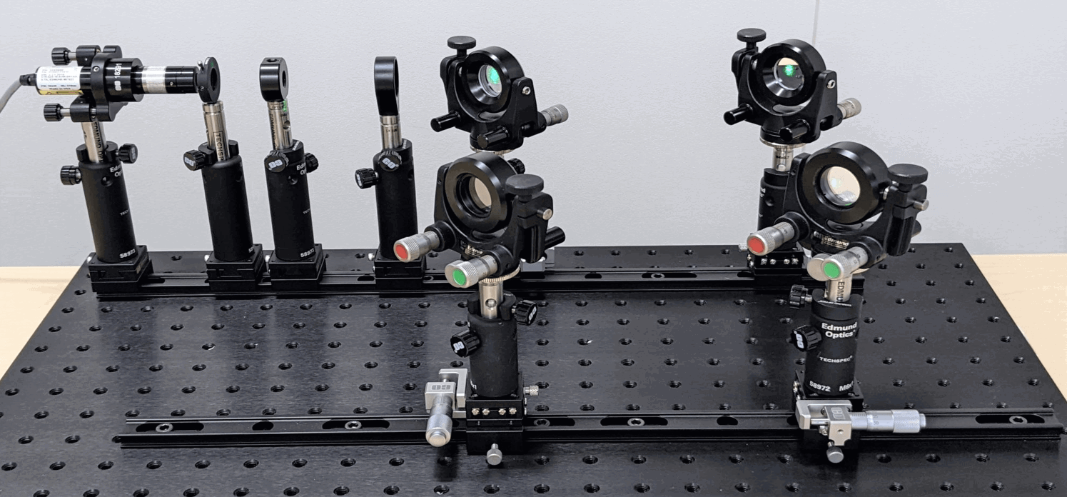
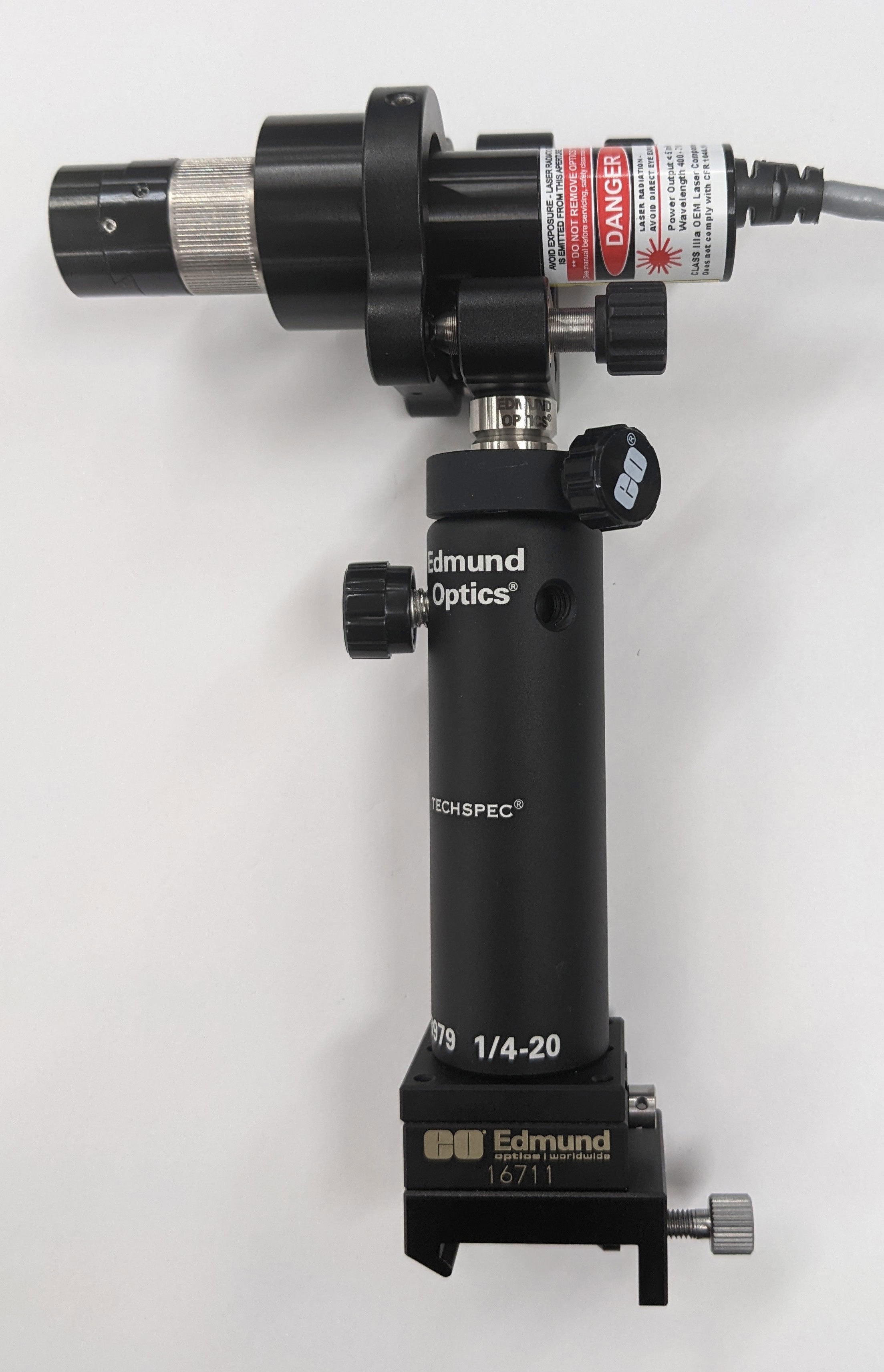
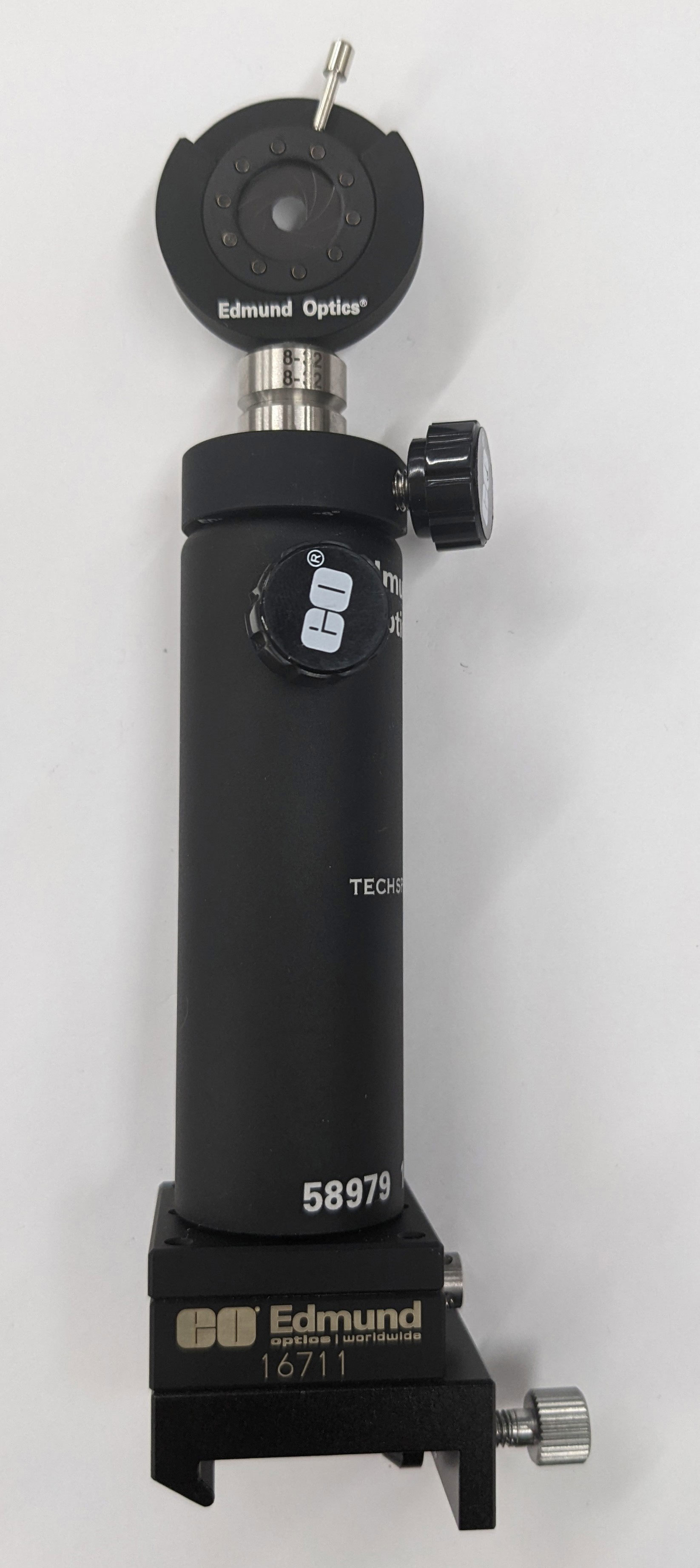
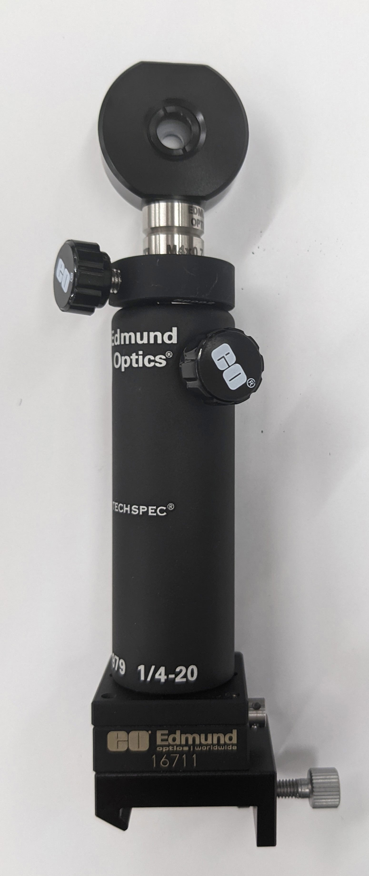
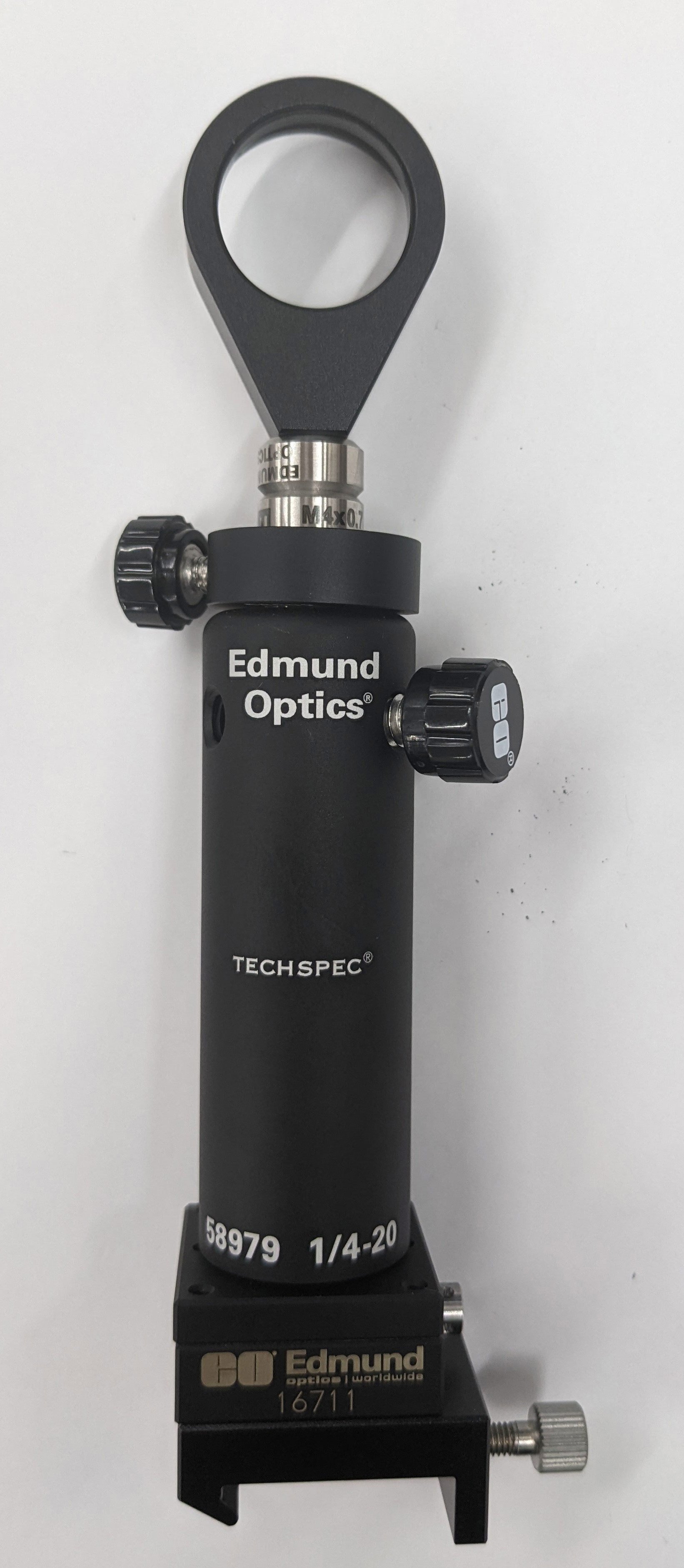
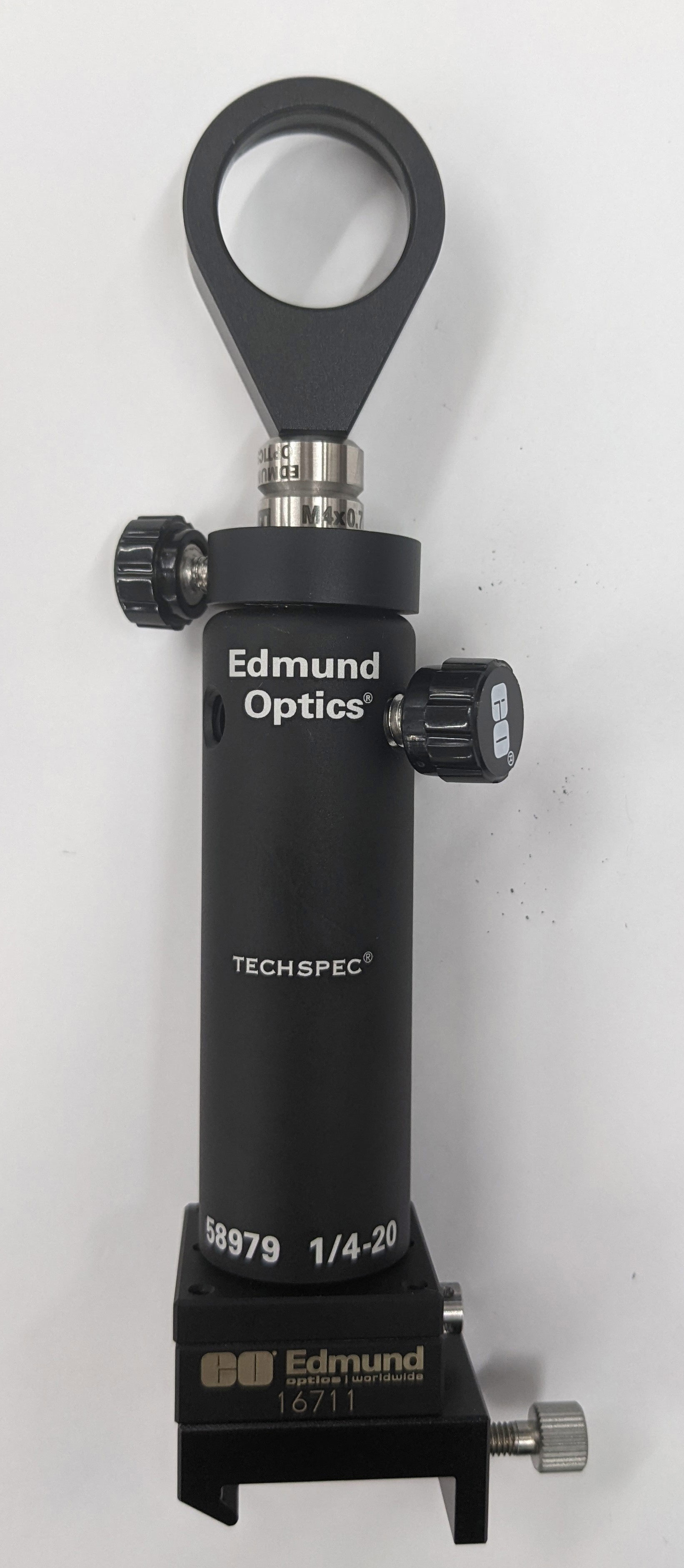
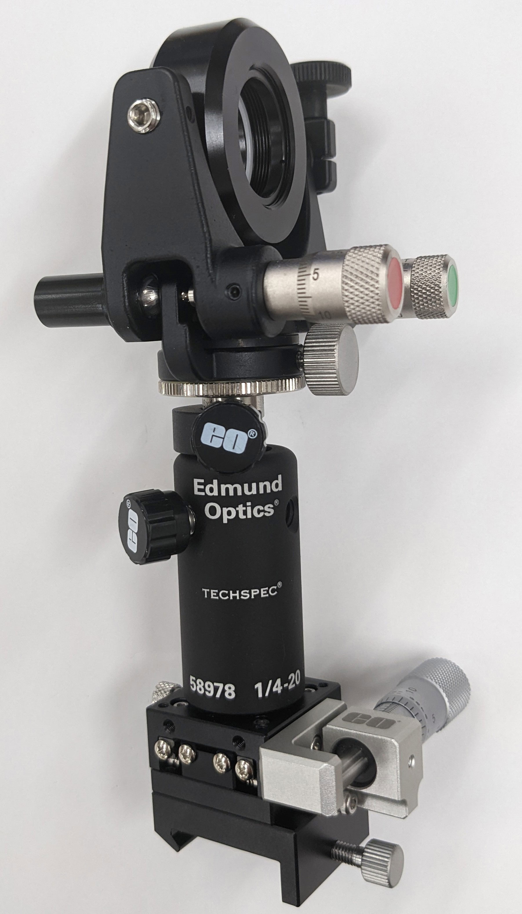
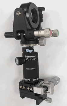
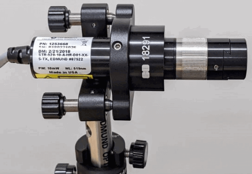 Figure 10: Installing the laser module


or view regional numbers
QUOTE TOOL
enter stock numbers to begin
Copyright 2024, Edmund Optics Singapore Pte. Ltd, 18 Woodlands Loop #04-00, Singapore 738100
California Consumer Privacy Acts (CCPA): Do Not Sell or Share My Personal Information
California Transparency in Supply Chains Act
This content may include material that has been generated or modified using artificial intelligence (AI).
The FUTURE Depends On Optics®