


Silhouetting Illumination in Machine Vision
Machine vision applications requiring precise detection and measurement of edges and small defects often demand challenging illumination set-ups. To maximize the contrast between an important detail and the background of an image, consider using an illumination technique called silhouetting illumination. When used in conjunction with a high quality telecentric imaging lens, a silhouetting lighting set-up will reduce scattering effects that may occur in other illumination systems, allow for more accurate edge detection, and provide better overall image contrast. There are four distinct illuminators that help create silhouetted illumination: conventional backlights, masked backlights, collimated backlights, and telecentric illuminators. Each illuminator has distinct advantages and disadvantages that, depending on the application, may be best integrated.
Divergence and Numerical Aperture
Before outlining the different types of silhouetting illuminators, reviewing the divergence and numerical aperture (NA) of both optical sources and imaging lenses is required. The divergence of a source is the angle that the light rays propagate at with respect to its optical axis. A divergent light source is one whose illumination profile grows in size as it moves away from its initial point, much like a standard flashlight. If an optical source does not appear to grow in size as it moves forward, the source is defined as a collimated light source, with the most common being a laser.
Collimated light occurs when the rays of a source propagate parallel to one another. This is achieved by using optics to manipulate a divergent beam or by placing a divergent source sufficiently far away from an object that it appears collimated by the time is reaches the object. By positioning a divergent source at a positive lens’s focal point, the rays will collimate after undergoing refraction. The size of the source and the specific lens used will determine how well collimated the resultant beam is. Equation 1 shows the relationship between left over divergence in the collimated beam θ, the diameter of a source D, and the collimating lens’s focal length f. This equation does not factor in other aspects that may affect the quality of a collimated beam, such as the shape factor of the lens, figure errors, or the roughness of the refractive surfaces. Equation 1 displays the tradeoff that is often necessary between resultant divergence and light collection. Figure 1 outlines a simple collimating set-up and demonstrates how the end diameter of the collimated beam is equal to that of the collimating lens used.
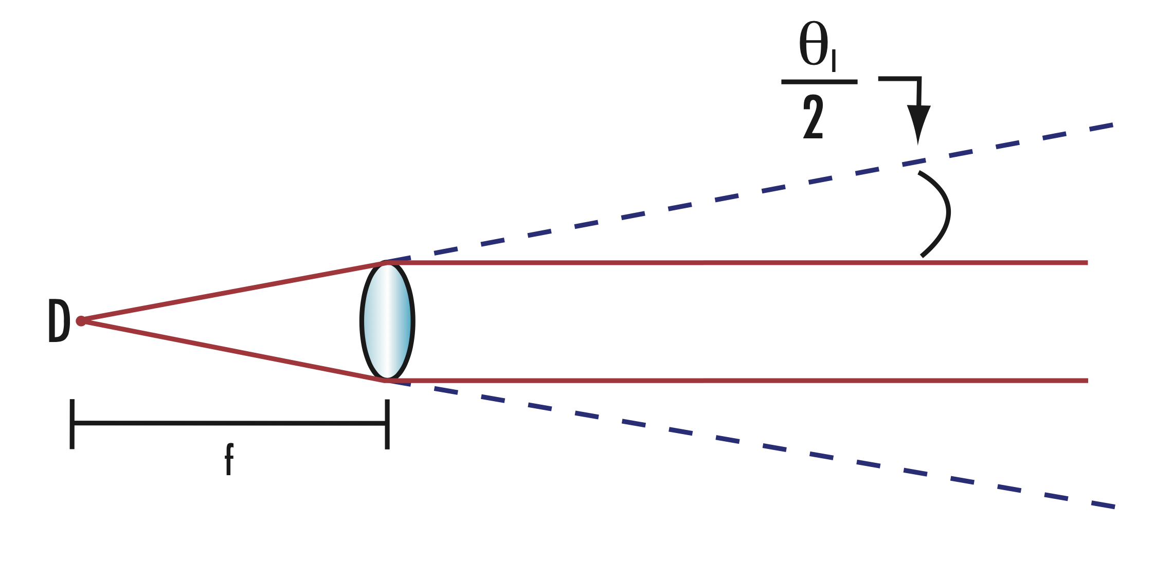
Figure 1: Divergent source collimation
The smaller the divergence of a light source, the better suited the light source is for silhouetting illumination. Figure 2 demonstrates how a collimated light and a divergent source interact differently with an object under inspection.
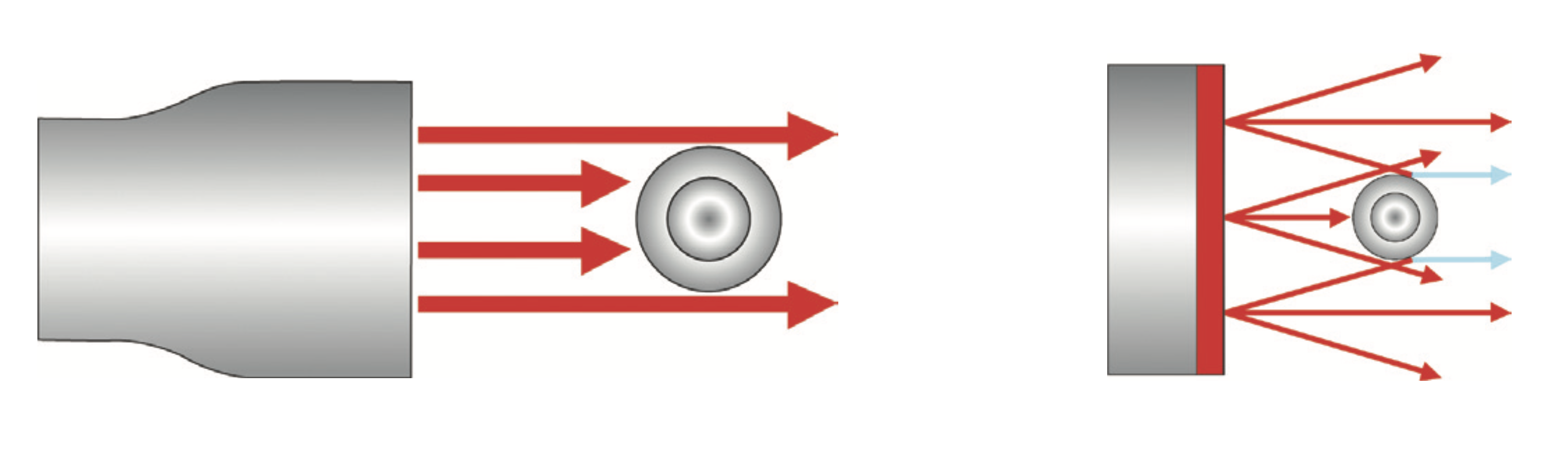
Figure 2: Divergent vs. collimated source
The rays of the divergent source hit the edges of an object at many different angles, which leads to light scattering (Figure 3). Scattered light varies based on the geometry and material properties, such as smoothness and reflectivity, of the part under inspection. This creates an effect where the scattered rays appear to originate within the physical boundaries of the part itself. The rays of the collimated source hit the object straight on, which dramatically reduces light scatter and creates a well-defined edge between the background and the silhouette.
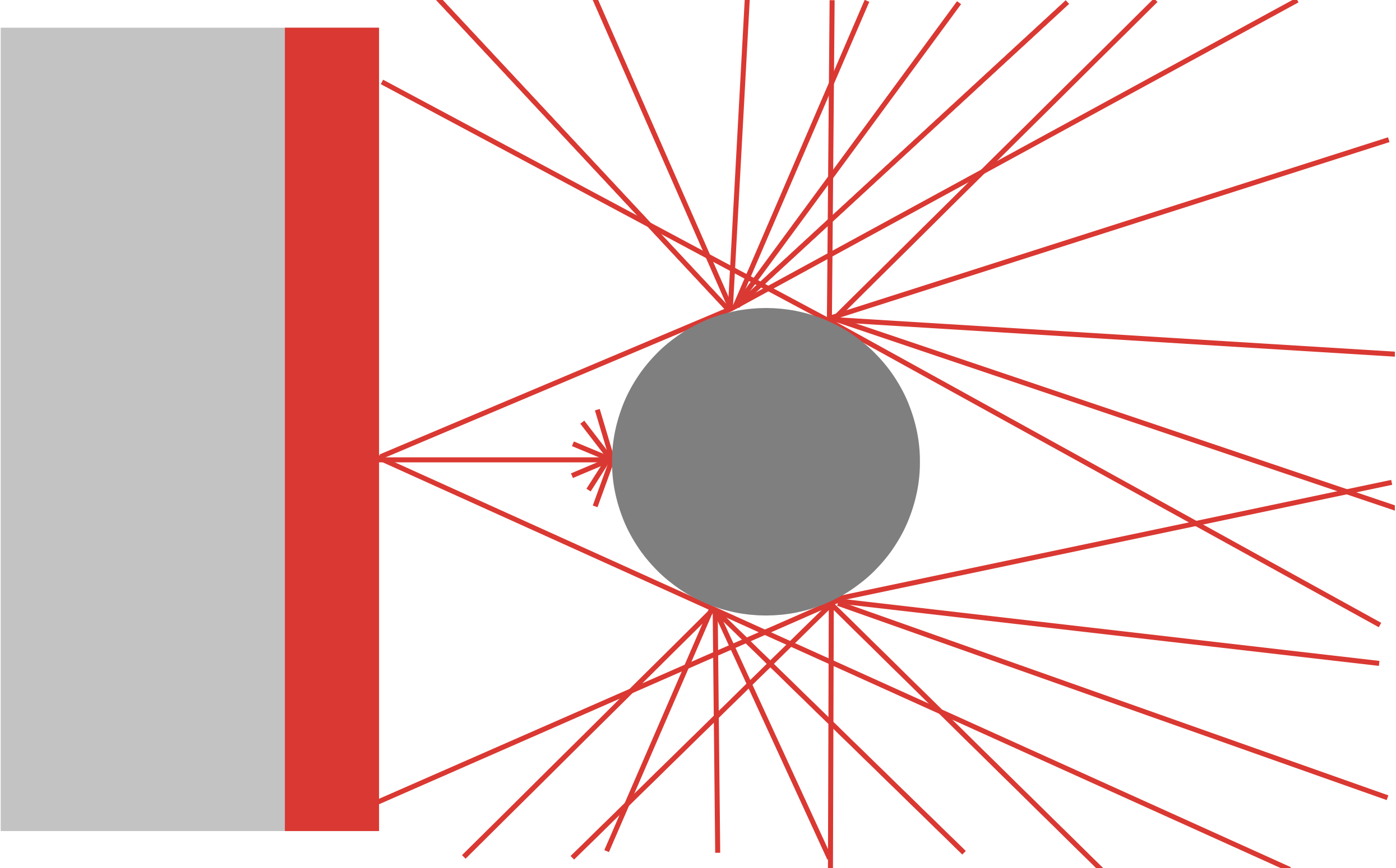
Figure 3: Light rays scattering off the edges of an object
Numerical aperture is one of the most important aspects to consider when choosing a suitable lens and illumination source pair for an imaging system. The numerical aperture of a lens is a unit-less number that describes its ability to collect off-axis light. Equation 2 shows that the NA of a source is defined by its divergence, θ.
The numerical aperture of an imaging lens may be included as part of the manufacturing specifications, but it may also be estimated using the inverse of its F-number (as in Equation 3). Because the two are directly related, the NA can also be used to define the resolution and depth of field of an imaging lens.
To maximize the efficiency of an imaging system, the numerical apertures of both the imaging lens and source should be as close to equal as possible. If the numerical aperture of the source is much larger than what the lens can handle, one may experience issues with scatter and stray light. When the NA of a lens is much larger than the source, an image may appear dim and lack sufficient contrast. In a silhouetting illumination set-up, a telecentric lens is often used as the imaging lens. Due to their construction, the telecentric lens’s magnification remains constant as they are moved closer or farther away from the object. This makes them ideal for applications where silhouetting illumination would be beneficial, such as gauging the shape and size of defects on an object. Telecentric lenses will often have smaller numerical apertures compared to standard fixed focal length imaging lenses, thereby making the illumination chosen even more critical.
Conventional Backlights
Conventional backlights are divergent light sources placed behind the object under inspection. They are often constructed by either placing many small light sources, such as LEDs or randomly oriented optical fibers, behind a diffuser to create a light source for use in less demanding silhouetting imaging setups. These light sources are commonly used when precise edge detection is not necessary such as in microscopy applications or with objects which are non-reflective. The additional advantages of these conventional backlights are their comparably lower price, wide availability and smaller construction, making them easy to integrate into space-constrained set-ups.
Figure 4: Fiber optic-based backlights
Because these types of backlights integrate divergent sources with a diffuser, the resultant light can often scatter off the edges of an object. This may be particularly noticeable if the object is metallic and reflective as shown in Figure 5.
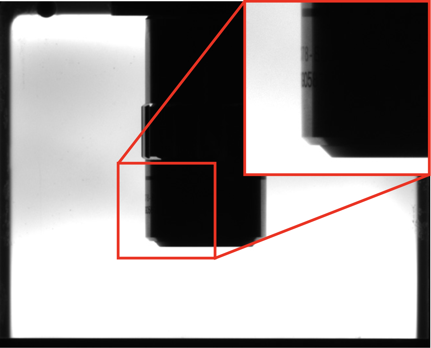
Figure 5: Silhouette of objective using conventional backlighting
This scatter will manifest as an edge that appears gradient and blurred, which may make it difficult for a user or software to pick out where the edge of an object is. Large amounts of scatter may also illuminate portions of the object that are unnecessary and cause misleading data to be taken. The edge profile shown in Figure 6 has the relative intensity of the edge go from bright to dark (high to low) over a range of about 30 pixels, with the lettering on the side of the objective causing ripples in the data.
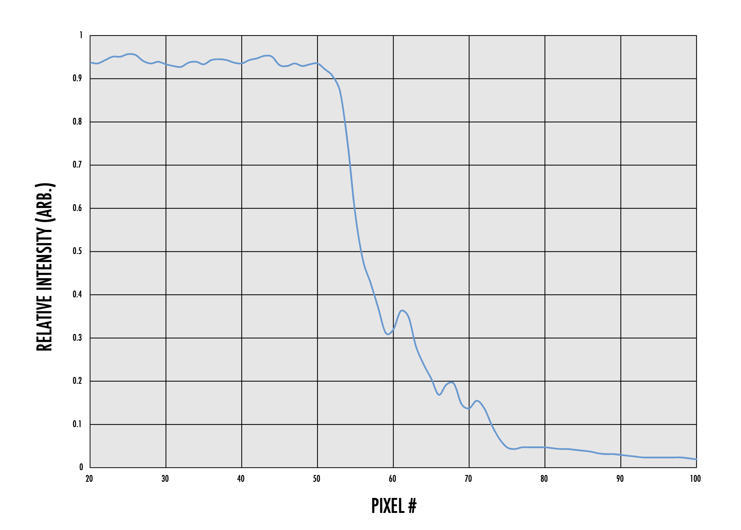
Figure 6: Edge profile obtained with conventional backlight
Masked Backlights
If scattered light at the edges of the silhouette obtained from a conventional, divergent backlight is unacceptable for an application, increasing the distance between the backlight and object will make the backlight’s rays appear less divergent. However, this is not always the best solution because if the backlight is too far away too much light may be lost. If the backlight is too close to the object, the scatter effect from the inherent divergence of the backlight remains problematic.
As shown in Figure 7, the object under inspection is often much smaller than the overall size of the backlight. This means that light rays from the unused portions of the backlight may also be hitting the edges of the object and cause larger and brighter edge scattering than it would be with just the rays near the edge interacting with the object. By masking the backlight, edge scattering can be reduced by blocking these extraneous rays.
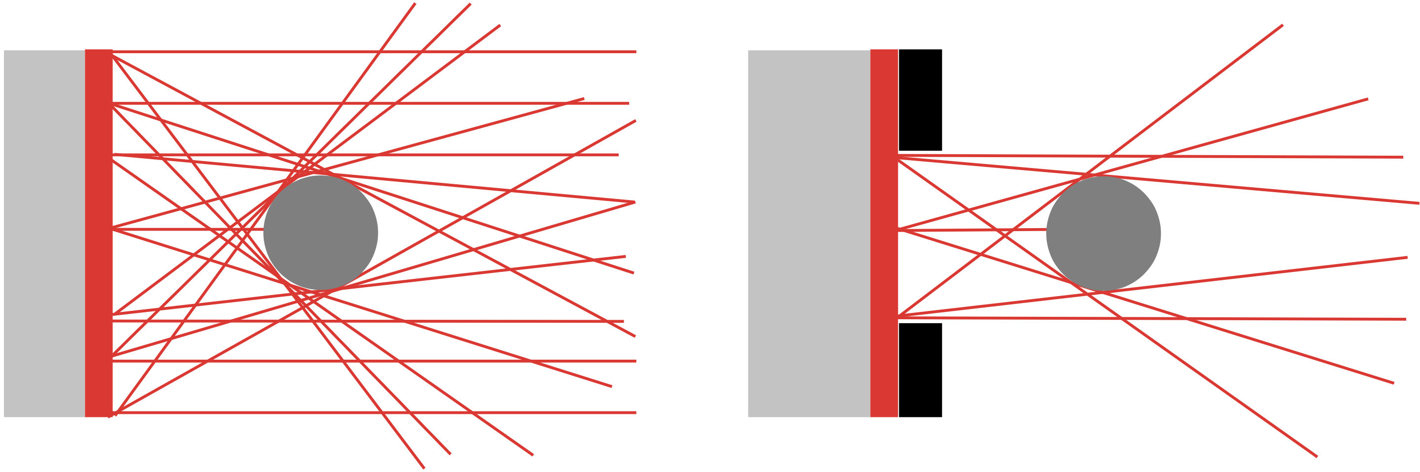
Figure 7: Conventional backlighting vs. masked backlighting
In order to mask a backlight, an opaque material such as flock paper should be used to block off portions of the backlight that are not necessary for the application. This method is advantageous because it is a quick and low-cost modification to a light. The downside is that the mask will not eliminate the edge scatter completely, and the light may need to be continually re-masked for different sized objects. Objects that are inspected as they move in the lens field of view also cannot effectively be masked. Figure 8 compares a backlight that has been masked to one that has not.
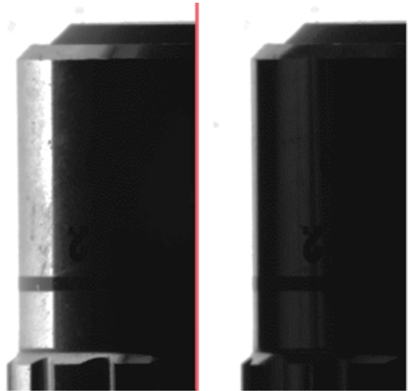
Figure 8: Edges of objective using conventional backlight (left) and masked backlighting (right)
Collimated Backlights
Similar in construction to conventional backlights, collimated backlights contain disparate divergent light sources and a diffuser, but have an additional collimating film to reduce the divergence of the backlight. This film only allows light rays within a certain angular range to exit, creating a lower divergence, low profile light source. This integrated film provides the benefit of low edge scatter without the hassle of masking an existing backlight for different sized objects.
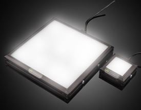
While these backlights are not truly collimated, the improvement is noticeable in silhouetting lighting setups. Figure 10 is an example of reduced edge scatter with a sharper profiled edge.
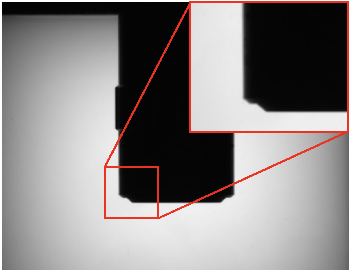
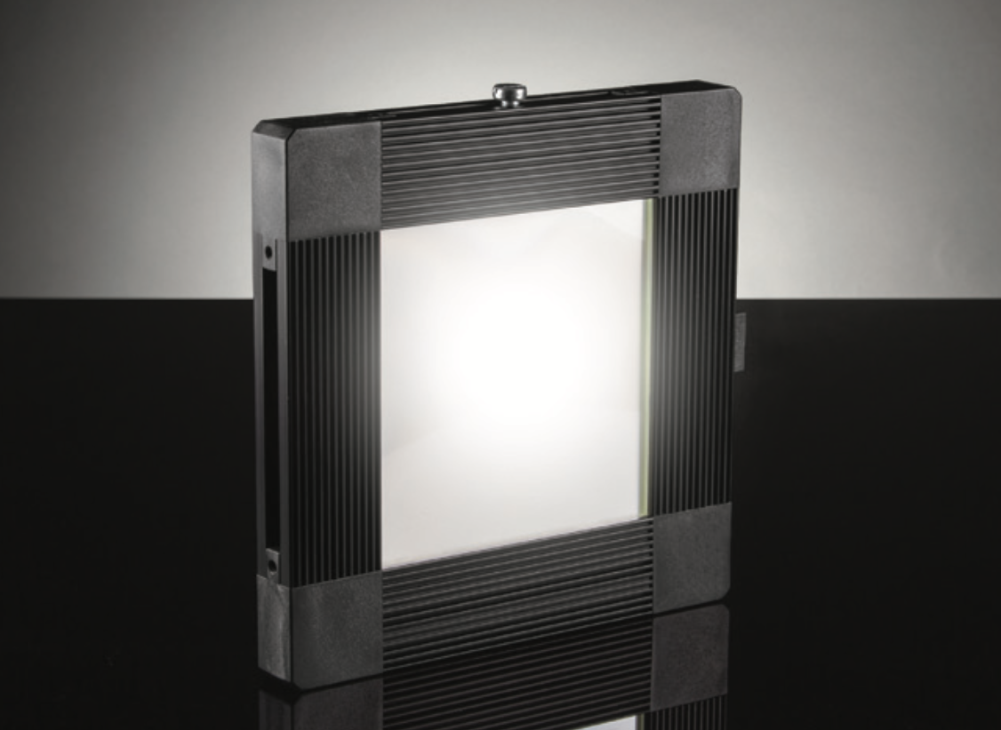
Figure 10: Advanced Illumination Edge-lit Collimated LED Backlight
The appearance of a clean edge is confirmed when looking at the intensity profile of the edge. Figure 11 demonstrates a much steeper slope in the transition from light to dark, taking place over about 20 pixels and does not suffer from the noise as in Figure 6.
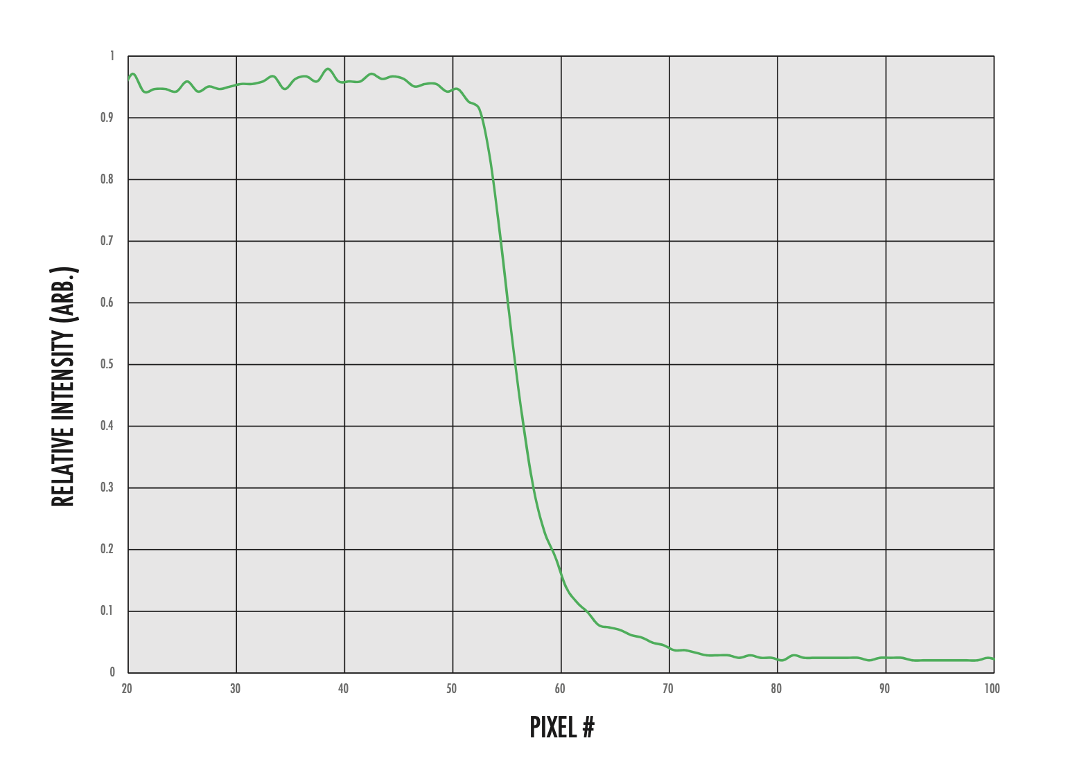
Figure 11: Edge profile obtained with collimated backlight
A collimated backlight is used where edge scatter is a concern, but space and budget restraints do not allow the use of a telecentric illuminator.
Telecentric Illuminators
When high precision applications demand the most accurate measurements, a telecentric illuminator should be considered as a light source. A telecentric illuminator works similarly to a telecentric imaging lens, but instead of the front optical elements projecting the aperture stop to infinity, it projects a light source. When these two optical systems are used in conjunction they offer superior performance and contrast compared to the previously mentioned backlight options.
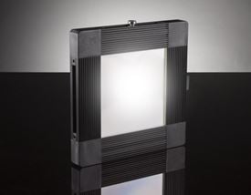
Figure 12: Telecentric illuminator
The main advantage of a telecentric illuminator is the high degree of collimation achieved through its optical design. Divergent LED sources are integrated into assemblies that create collimated rays, typically within less than a degree of true collimation. These types of telecentric illuminators are constructed by precisely positioning a large positive lens and a small powerful LED, creating an illumination profile that creates sharp silhouettes and matches the NA of a telecentric imaging lens better than other backlighting methods. Figure 13 shows the same object from Figure 10 back lit by a telecentric illuminator. The object exhibits none of the edge scatter effects seen from a conventional backlight and a sharper edge transition compared to the collimated backlight. Figure 14 confirms this sharp transition, with the slope from light to dark occurring over less than 10 pixels.
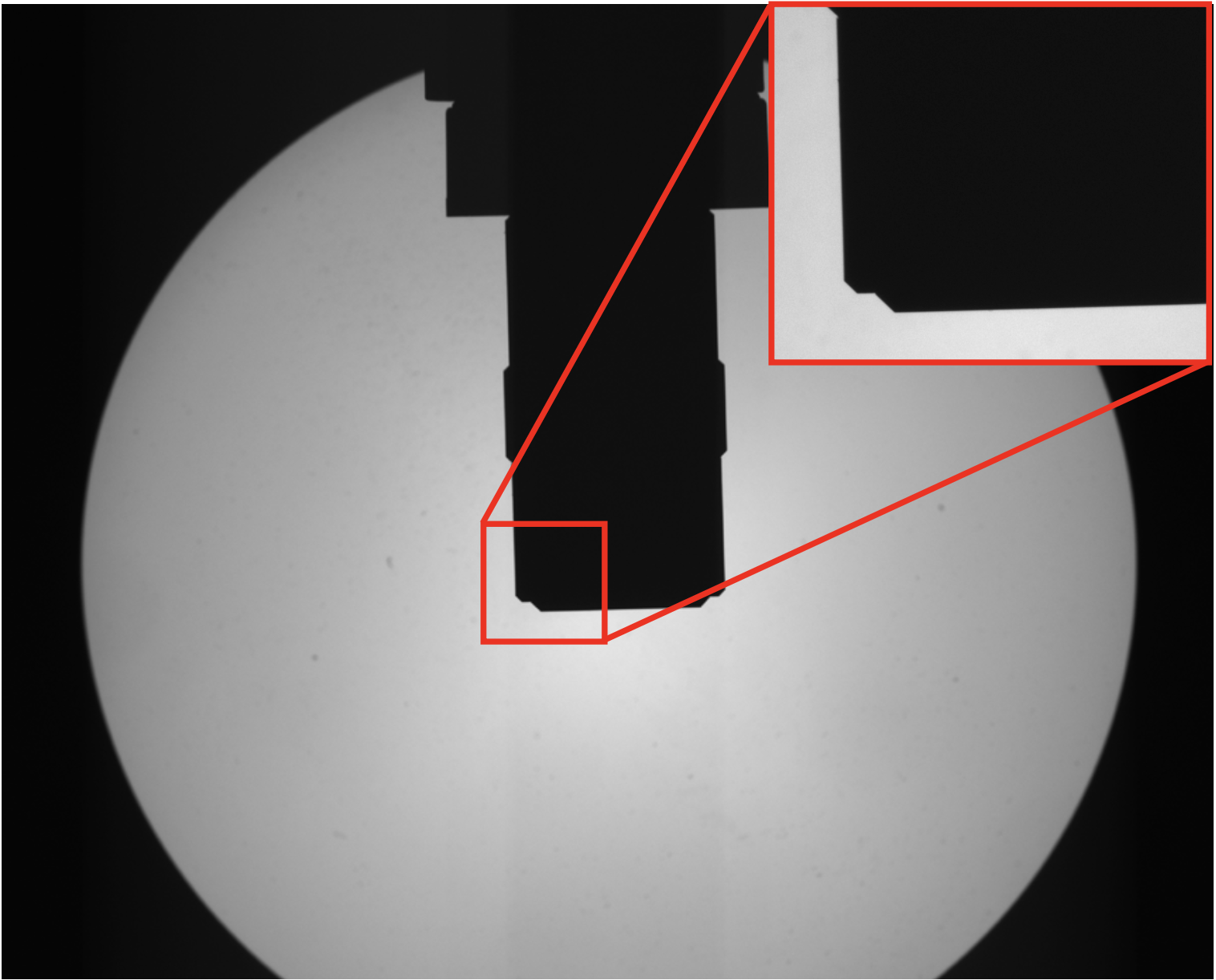
Figure 13: Silhouette of objective using a telecentric backlight
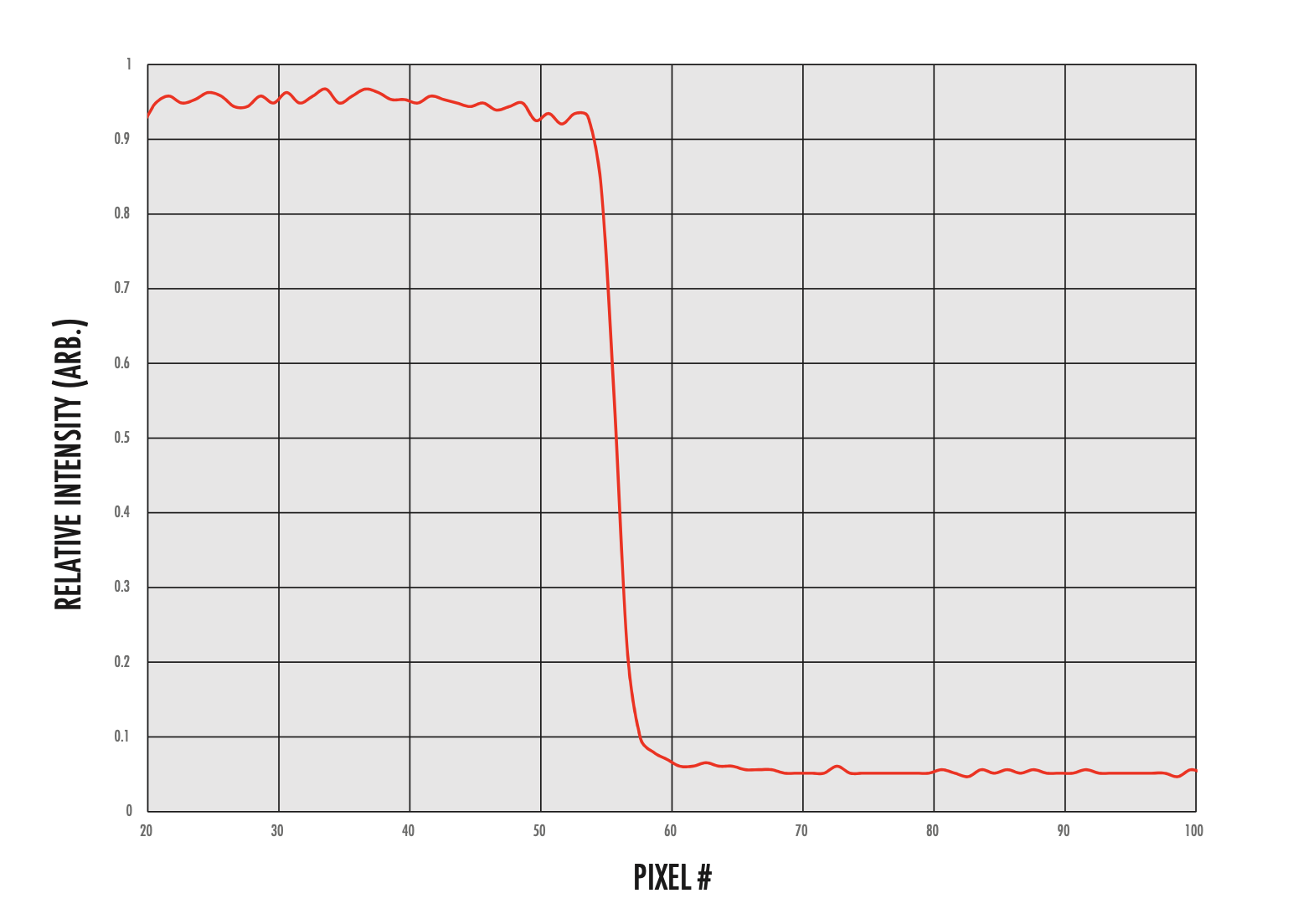
Figure 14: Edge profile obtained with telecentric illuminator
Achieving these high contrast silhouettes does have its disadvantages. Often telecentric illuminators are higher in cost and much larger than the previously discussed backlighting options. Because of the optical design of a telecentric lens, the size of the front element will determine the size of the illuminated spot. If a large FOV is needed, a large telecentric illuminator will be necessary, increasing system size and weight. Additionally, the low NA of a source helps create an image free from scatter effects, but can make alignment more difficult. If the alignment between the telecentric illuminator and lens are off even by a degree, the spot created by the illuminator will appear extremely dim and edge contrast will be reduced. Figure 15 shows how quickly the profile suffers when a lens and illuminator are out of alignment.

Figure 15: Illuminated spots produced in alignment (left) and 20 arcmin out of alignment (right)
The manufacturer’s specifications of a telecentric illuminator may sometimes lead to confusion. A working distance value is a meaningful specification when used with a telecentric imaging lens, as it describes the physical distance (or range of distances) the lens can focus properly. A telecentric illuminator does not focus light or create an image, so this number is often not useful. Because of the efficient light collection and collimation in a well-made telecentric illuminator, the physical distance between the light and an object can be much larger than a stated as a working distance. When considering a telecentric illuminator, the most applicable specifications are the maximum diameter of the collimated light beam, the physical size of the lens, and the numerical aperture. These specifications provide the basis for choosing an appropriate lighting and lens combination.
Conclusion
Figure 16 shows the edge profiles of the same object plotted against one another as a comparison over how many pixels the transition between the bright background and the dark edge takes place. The telecentric illuminator has the quickest and most consistent cutoff, while the collimated backlight has a consistent slope that takes place over about twice the amount of pixels. The slope from the conventional backlight has a similar profile to the collimated backlight at first, but the additional scattering induced by the high divergence of the backlight shows that the profile struggles to quickly reach darker intensities. The inconsistencies in the conventional backlight profile are from lettering on the edge of the object that is only visible due to the higher edge scattering, highlighting another possible issue when using a conventional backlight
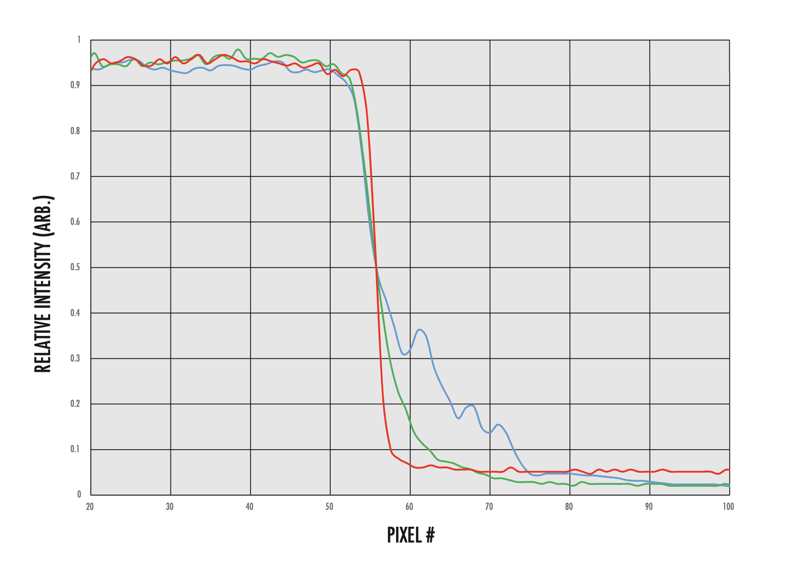
Figure 16: Combined edge profiles obtained using conventional backlighting (blue), collimated backlighting (green), and telecentric illumination (red)
Knowing the most important aspects of a lighting set-up for your application will ultimately help make a more informed backlight choice.
| TYPE OF LIGHTING | ADVANTAGES | DISADVANTAGES |
|---|---|---|
| Conventional Backlight | Low cost | High divergence creates edge scattering |
| Low profile | High NA leads to wasted light | |
| Easy to set-up and align | Fair to poor uniformity | |
| Masked Backlight | Lowers scatter vs conventional backlights | Not a "one-size-fits-all" approach |
| Easy & low cost modification to existing backlight | Similar disadvantages to conventional in un-masked portions | |
| Collimated Backlight | Smaller divergence to reduce edge scattering | Not truly collimated |
| Larger sizes available in smaller package | Inefficient when paired with low NA Telecentric lenses | |
| High uniformity | Higher cost compared to conventional backlights | |
| Telecentric Illuminator | Lowest divergence creates highest contrast silhouettes | Higher cost |
| Allows for a greater separation of light source and object | Larger size | |
| High uniformity | Alignment sensitive | |
Table 1: Advantages and disadvantages of silhouetting illumination method
Silhouetting illumination can be produced with different types of backlights and the best choice will ultimately depend on your specific application. It may be tempting to use a standard backlight because of space and cost concerns, but this often leads to unacceptable scattering and poor edge contrast. Masking the unused portions of these backlights can help, but can be a time-consuming process if multiple sized objects are under inspection. Collimated backlights are often lower in cost and smaller in size compared to telecentric illuminators, but may not satisfy applications that require high precision. Telecentric illuminators provide the overall best uniformity and most accurate edge detection, but may not fit into every set-up due to their larger size and higher cost.
Related Products
 Telecentric Backlight Illuminators
- Optically Collimated Light for Increased Edge Contrast
- Superior Collimation Ideal for use with Telecentric Lenses
- Easily Compatible with 8mm Coaxial LEDs or ¼” (0.312”) Fiber Light Guides
Advanced Illumination Edge-lit Collimated LED Backlights
- Collimated Light Source for Precision Silhouetting Applicationst
- High Intensity and Low Heat Output
- Low Divergence Angles Compared to Non-Collimated Backlights
More Backlights
- Wide Variety of Silhouetting Illumination Options for Machine Vision
- P69K Certified Options for Extreme Washdown Environments
- High Intensities for High Imaging Contrast


or view regional numbers
QUOTE TOOL
enter stock numbers to begin
Copyright 2024, Edmund Optics Singapore Pte. Ltd, 18 Woodlands Loop #04-00, Singapore 738100
California Consumer Privacy Acts (CCPA): Do Not Sell or Share My Personal Information
California Transparency in Supply Chains Act
This content may include material that has been generated or modified using artificial intelligence (AI).
The FUTURE Depends On Optics®