


Understanding Waveplates and Retarders
Terminology | Fabrication | The Right Waveplate | Applications
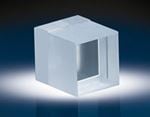
 Waveplates, also known as retarders, transmit light and modify its polarization state without attenuating, deviating, or displacing the beam. They do this by retarding (or delaying) one component of polarization with respect to its orthogonal component. In unpolarized light, waveplates are equivalent to windows – they are both flat optical components through which light passes. Understanding waveplates as they pertain to polarized light is a bit more complex. To simplify the process, consider key terminology and specifications, fabrication, common types, and application examples.
WAVEPLATE TERMINOLOGY AND SPECIFICATIONS
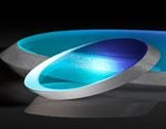
Birefringence - Waveplates are made from birefringent materials, most commonly crystal quartz. Birefringent materials have slightly different indices of refraction for light polarized in different orientations. As such, they separate incident unpolarized light into its parallel and orthogonal components (Figure 1).
Figure 1: Birefringent Calcite Crystal Separating Unpolarized Light
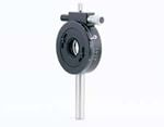
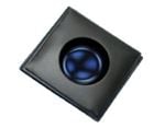
Fast Axis and Slow Axis - Light polarized along the fast axis encounters a lower index of refraction and travels faster through waveplates than light polarized along the slow axis. The fast axis is indicated by a small flat spot or dot on the fast axis diameter of an unmounted waveplate, or a mark on the cell mount of a mounted waveplate.
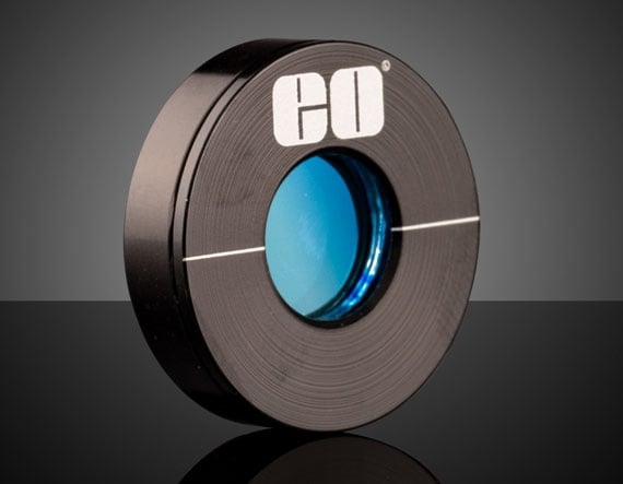
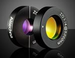
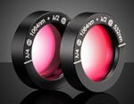
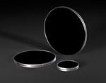
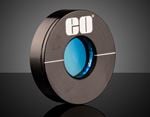
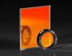
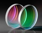
Figure 2: An Edmund Optics® Precision Zero Order Waveplate (Retarder) showing the white indicator line on the cell mount
Retardation – Retardation describes the phase shift between the polarization component projected along the fast axis and the component projected along the slow axis. Retardation is specified in units of degrees, waves, or nanometers. One full wave of retardation is equivalent to 360°, or the number of nanometers at the wavelength of interest. Tolerance on retardation is typically stated in degrees, natural or decimal fractions of a full wave, or nanometers. Examples of typical retardation specifications and tolerances are:
λ/4 ± λ/300
λ/2 ± 0.003λ
λ/2 ± 1°
430nm ± 2nm
The most popular retardation values are λ/4, λ/2, and 1λ, but other values can be useful in certain applications. For example, internal reflection from a prism causes a phase shift between components that may be troublesome; a compensating waveplate can restore the desired polarization.
In Figure 3 below, 4 retardation values are shown relative to an original, sine wave. The orange wave is retarded by a quarter of a wave, the yellow by a half, the green by three-quarters, and lastly, the blue by a full wave. The retardation by a quarter wave changes the sine wave to a cosine wave and the full wave retardation lets the wave elapse itself. The most popular waveplates are quarter and half waveplates since they can be stacked to achieve additional retardation values.
Figure 3a: Retardations of an electric field wave
Multiple Order – In multiple order waveplates, the total retardation is the desired retardation plus an integer. The excess integer portion has no effect on the performance, in the same way that a clock showing noon today looks the same as one showing noon a week later – although time has been added, it still appears the same.
Although multiple order waveplates are designed with only a single birefringent material, they can be relatively thick, which eases handling and system integration. The high thickness, though, makes multiple order waveplates more susceptible to retardation shifts caused by wavelength shift or ambient temperature changes.
Zero Order – In zero order waveplates, the total retardation is the desired value without excess. For example, Zero Order Quartz Waveplates consist of two multiple order quartz waveplates with their axes crossed so that the effective retardation is the difference between them.
The standard zero order waveplate, also known as a compound zero order waveplate, consists of multiple waveplates of the same birefringent material that have been positioned so that they are perpendicular to the optical axis. Layering multiple waveplates counterbalances the retardation shifts that occur in the individual waveplates, improving retardation stability to wavelength shifts and ambient temperature changes. Standard zero order waveplates do not improve retardation shift caused by a different angle of incidence.
True zero order waveplates, such as Polymer Waveplates, are comprised of a single birefringent material that has been processed into an ultra-thin plate that may be only a few microns thick in order to achieve a specific level of retardation at zero order. While the thinness of the plate may make handling or mounting the waveplate more difficult, true zero order waveplates offer superior retardation stability to wavelength shift, ambient temperature change, and a different angle of incidence than other waveplates.
Achromatic – Achromatic waveplates consist of two different materials that practically eliminate chromatic dispersion. Standard achromatic lenses are made from two types of glass, which are matched to achieve a desired focal length while minimizing or removing chromatic aberration. Achromatic waveplates operate on the same basic principle. For example, Achromatic Waveplates are made from crystal quartz and magnesium fluoride to achieve nearly constant retardation across a broad spectral band.
Super Achromatic – Super achromatic waveplates are a special type of achromatic waveplate which are used to eliminate chromatic dispersion for a much broader waveband. Many super achromatic waveplates can be used for both the visible spectrum as well as the NIR region with close to the same, if not better, uniformity than typical achromatic waveplates. Where typical achromatic waveplates are made of quartz and magnesium fluoride of specific thicknesses, super achromatic waveplates use an extra sapphire substrate along with quartz and magnesium fluoride. The thickness of all three substrates is determined strategically to eliminate chromatic dispersion for a longer range of wavelengths.
FABRICATION AND CONSTRUCTION
Fabrication
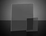
Waveplates are particularly challenging optical components to manufacture. They are made of crystalline materials that must be cut with their axes oriented within a few arcminutes. Then, they must be polished to a laser-quality finish, arcsecond parallelism, and <λ/10 wavefront. There is no room for correction, as their thickness tolerance is a small fraction of a micron. To verify retardation tolerances, specially-trained optical technicians use purpose-built test gear. After anti-reflective coating, zero order and achromatic waveplates are matched in pairs and accurately aligned to each other within their cell mounts.
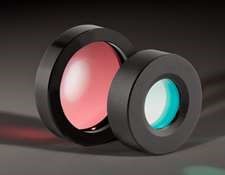
Quartz waveplates are ideal for applications requiring high damage thresholds and retardation stability over temperature change, such as for use with lasers or infrared light sources.
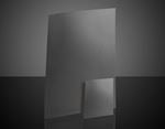
Polymer waveplates consist of thin polymer sheets laminated between two glass plates, and provide many of the benefits of zero order designs including excellent angular field-of-view and lower sensitivity to incidence angles than comparable quartz waveplates. While the glass plates increase durability and ease handling, many polymer waveplates contain adhesive layers and are therefore not recommended for high power laser or high temperature applications.
Construction
Multiple order waveplates consist of a single plate, either unmounted or edge mounted to an aluminum cell. Two common construction methods exist for Precision Zero Order Waveplates and Achromatic Waveplates. The first method utilizes an air gap where the two plates, coated on all faces, are mounted on opposite sides of a spacer and then placed within a cell. Typical beam deviation is <0.5 arcseconds. It is important to note that power handling, especially for pulsed lasers, is highly suggested when using waveplates constructed with air gaps. The second method involves cementing achromatic lenses together with a transparent layer of optical cement across their full diameters. Then, an anti-reflection coating is applied to only their outer surfaces. Transmitted wavefront is <λ/4 at 633nm; beam deviation is <1 arcminute.
CHOOSING THE RIGHT WAVEPLATES
Multiple Order Waveplates
Consisting of a single plate of crystal quartz (nominally 0.5mm in thickness), multiple order waveplates are the least expensive of the three types. Their retardation changes versus temperature (Figure 4), and changes substantially versus wavelength (Figure 5). They are a good choice for use with monochromatic light in a climate-controlled environment. They are typically coupled with a laser in a laboratory. In contrast, applications such as mineralogy exploit the chromatic shift (retardance versus wavelength change) inherent in multiple order waveplates.
Figure 4: Retardance vs. Temperature for a 7.25λ Multiple Order Waveplate at 632.8nm
Figure 5: Retardance vs. Wavelength for a 7.25λ Multiple Order Waveplate at 632.8nm
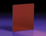
An alternative to conventional crystalline quartz waveplates is Polymer Retarder Film. This film is available in several sizes and retardances and at a fraction of the price of crystalline waveplates. Film retarders are superior to crystal quartz application-wise in terms of flexibility. Their thin polymeric design allows for easy cutting of the film to the shape and size necessary. These films are ideal for use in applications that use LCDs and fiber optics. Polymer Retarder Film is also available in achromatic versions. This film however, has a low damage threshold and should not be used with high powered light sources like lasers. Additionally, its use is limited to the visible spectrum, so UV, NIR, or IR applications will require an alternative.
Zero Order Waveplates
As their total retardation is a small percentage of the multiple order type, the retardation for zero order waveplates is far more constant with respect to temperature (Figure 6) and wavelength variations (Figure 7). In situations requiring greater stability or requiring greater temperature excursions, zero order waveplates are the ideal choice. Application examples include observing a broadened spectral wavelength, or taking measurements with an instrument used in the field.
Figure 6: Retardance vs. Temperature for a λ/4 Zero Order Waveplate at 632.8nm
Figure 7: Retardance vs. Wavelength for a λ/4 Zero Order Waveplate at 632.8nm
Achromatic Waveplates
Due to the compensation of two materials, achromatic waveplates are far more constant than even zero order waveplates (Figure 8). If the situation covers several spectral wavelengths or an entire band (from violet to red, for example), achromatic waveplates are the ideal choices.
Figure 8: Retardance vs. Wavelength for a 610 – 850nm Achromatic Waveplate
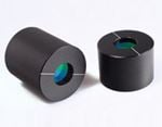
Fresnel Rhomb Retarders
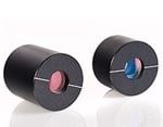
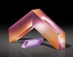
Fresnel Rhomb Retarders utilize internal reflection at specific angles within the prism structure to impart a retardance to incident polarized light. Each reflection of light typically advances the p-polarized light component by λ/8. As the light exits the prism having reflected from two surfaces, the total retardance through a singular rhomb retarder is λ/4. Additionally, two rhomb retarders can be cemented together to achieve a λ/2 retardance version as well. The variation in retardance is within 2% across the wavelength range. These retarders are optimized for use with diode and fiber applications. Because Fresnel Rhomb Retarders function based on total internal reflection, they can be used for broadband or achromatic use.
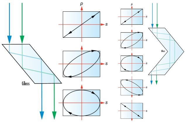
Figure 9: λ/4 Retardance Fresnel Rhomb Retarder (left) and λ/2 Retardance Fresnel Rhomb Retarder (right)
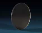
Crystalline Quartz Polarization Rotators
Crystalline Quartz Polarization Rotators are single crystals of quartz that rotate the polarization of incident light independent of the alignment between the rotator and the light’s polarization. This is due to the optical activity of the quartz associated with the crystal structure. Quartz has two enantiomorphs, which means that the crystal lattice of SiO4 can form two different structures that are mirror images of each other. Whichever structure the crystal has will determine whether the light polarization is advanced in a clockwise or counter-clockwise direction. Because they rotate the polarization plane by a specific angle, Crystalline Quartz Polarization Rotators are a great alternative to waveplates and can be used to rotate the entire polarization of the light along the optical axis, not just a singular component of the light. The direction of propagation of incident light must be perpendicular to the rotator.
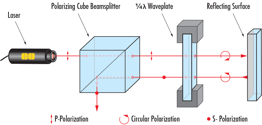
Figure 10: A Crystalline Quartz Polarization Rotator Shown Rotating an Incoming Polarization by 90°
APPLICATION EXAMPLES
Rotating Linear Polarization
It is sometimes necessary to alter the existing polarization of an optical system. For example, lasers are typically horizontally polarized. If the system calls for laser light to reflect off a metallic surface, then this can be a problem because mirrors work best with vertically polarized light. What is the solution? A λ/2 waveplate with its axes oriented at 45° will rotate the polarization to vertical.
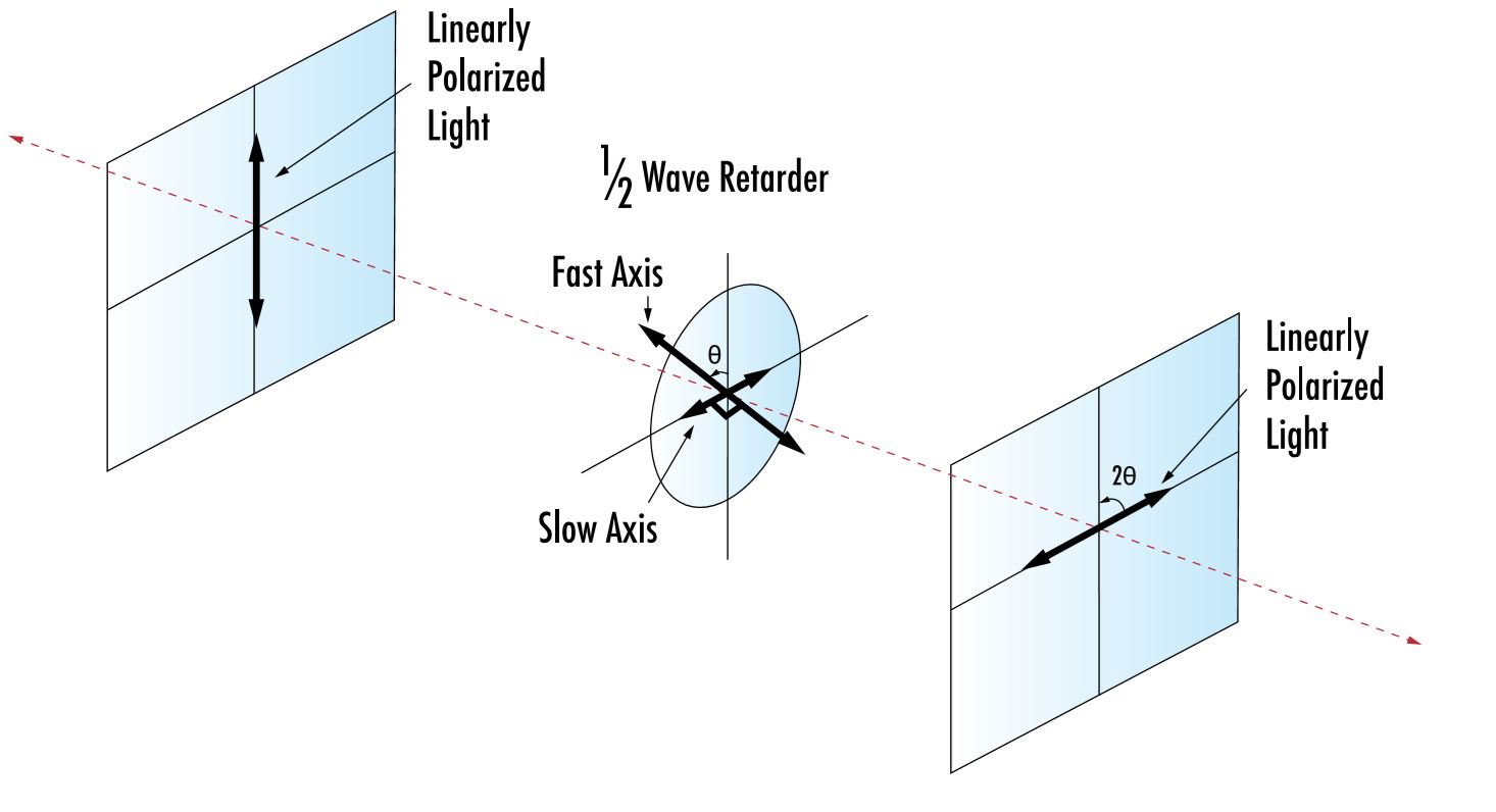
Figure 11: Rotating Linear Polarization from Vertical to Horizontal with a λ/2 Waveplate
Another example is when it is desirable to adjust the polarization axis to any other orientation. Rotating the waveplate axis an angle of θ from the incident polarization will rotate the exiting polarization by 2θ. Since waveplates are highly parallel, inserting or rotating a λ/2 waveplate can reconfigure an entire optical setup with no realignment.
Transforming between Linear and Circular Polarization
Linearly polarized light can be transformed into circularly polarized light, and vice versa, by orienting a linear polarizer and λ/4 waveplate in a certain way. For example, a λ/4 waveplate with its axes oriented at 45° to linear polarization produces circular polarization. Circular polarization, which is of indeterminate orientation, passing through a λ/4 waveplate produces linear polarization at 45° to the waveplate’s axis. Additionally, if linearly polarized light enters a λ/4 waveplate at any angle besides 45°, it becomes elliptically polarized.
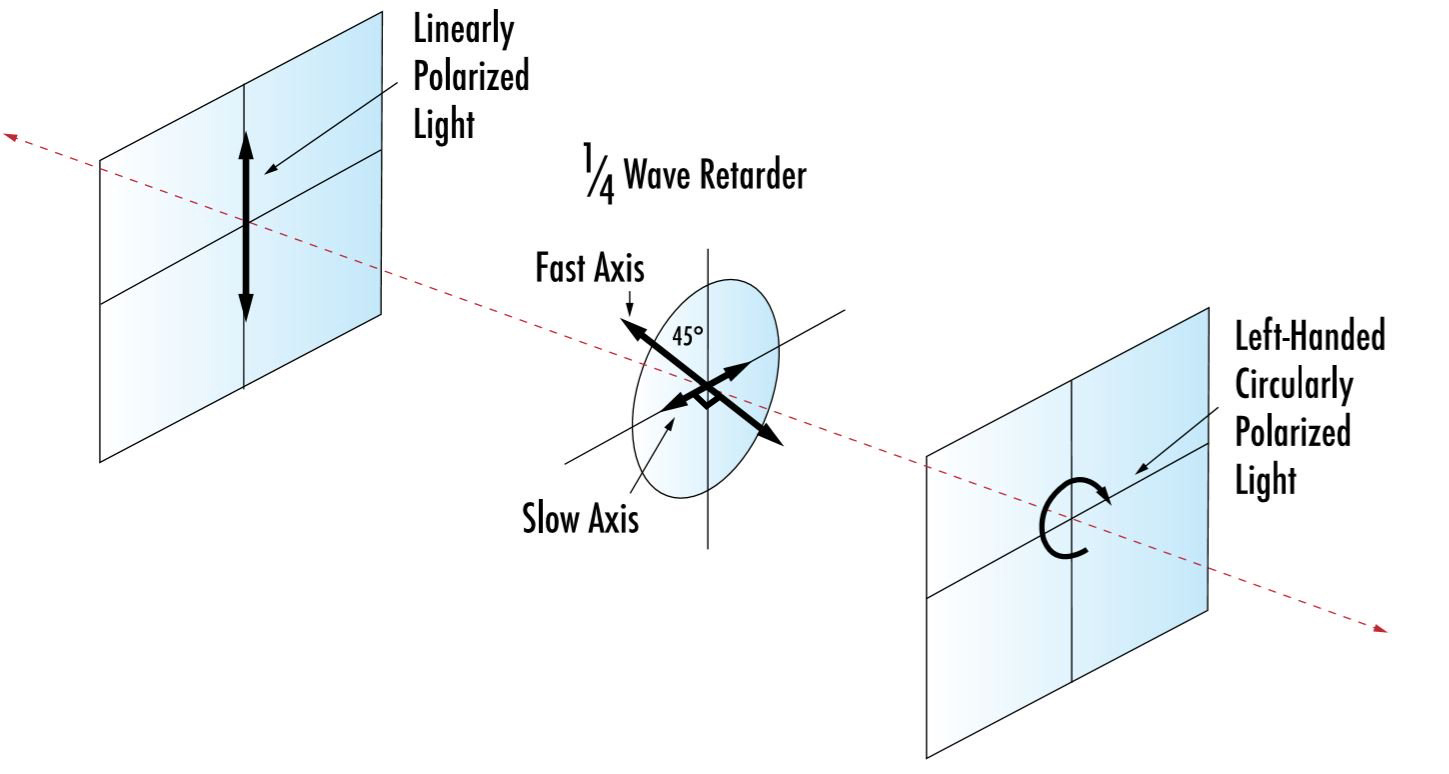
Figure 12: Circularizing Linear Polarization with a λ/4 Waveplate
Optical Isolation with a Linear Polarizer
A linear polarizer plus a λ/4 waveplate creates an optical isolation system where light polarized by the linear polarizer passes through the λ/4 waveplate without attenuation but is transformed to circular polarization. If reflected from a mirror, the circularly polarized light encounters the waveplate again and is returned to linear polarization, but rotated 90° (Figure 13). Note: Two passes of a λ/4 are equivalent to one pass of a λ/2. The reoriented light is rejected by the linear polarizer. This system uses a double pass technique to remove feedback.

Figure 13: Rotating Linear Polarization with a λ/2 Waveplate
Optical Isolation with a Beamsplitter: Efficient Routing
A polarizing beamsplitter can be substituted for the linear polarizer in the optical isolation application example from Figure 13. This redirects the returning light into an alternate path without attenuation (Figure 14). By contrast, double pass through a non-polarizing beamsplitter only returns a theoretical maximum of 25% into the desired path and 25% into the other path.

Figure 14: Polarizing Beamsplitter and λ/4 Waveplate System Illustrating Optical Isolation
Waveplates are ideal for controlling and analyzing the polarization state of light. They are offered in three main types – zero order, multiple order, and achromatic – each containing unique benefits depending upon the application at hand. A strong understanding of key terminologies and fabrication methods helps in choosing the right waveplate, no matter how simple or complex the optical system.


or view regional numbers
QUOTE TOOL
enter stock numbers to begin
Copyright 2023, Edmund Optics Inc., 18 Woodlands Loop #04-00, Singapore 738100
California Consumer Privacy Act (CCPA): Do Not Sell or Share My Personal Information
California Transparency in Supply Chains Act