


Understanding Optical Specifications
Manufacturing Specifications | Surface Specifications | Material Specifications
Optical specifications are utilized throughout the design and manufacturing of a component or system to characterize how well it meets certain performance requirements. They are useful for two reasons: first, they specify the acceptable limits of key parameters that govern system performance; second, they specify the amount of resources (i.e. time and cost) that should be spent on manufacturing.
An optical system can suffer from either under-specification or over-specification, both of which can result in unnecessary expenditure of resources. Under-specification occurs when not all of the necessary parameters are properly defined, resulting in inadequate performance. Over-specification occurs when a system is defined too tightly without any consideration for changes in optical or mechanical requirements, resulting in higher cost and increased manufacturing difficulty.
In order to understand optical specifications, it is important to first review what they mean. To simplify the ever-growing number, consider the most common manufacturing, surface, and material specifications for lenses, mirrors, and windows. Filters, polarizers, prisms, beamsplitters, gratings, and fiber optics also share many of these optical specifications, so understanding the most common specifications will provide a great baseline for understanding nearly all optical products.
Manufacturing Specifications
Diameter Tolerance
The diameter tolerance of a circular optical component provides the acceptable range of values for the diameter. This manufacturing specification can vary based on the skill and capabilities of the particular optical shop that is fabricating the optic. Although diameter tolerance does not have any effect on the optical performance of the optic itself, it is a very important mechanical tolerance that must be considered if the optic is going to be mounted in any type of holder. For instance, if the diameter of an optical lens deviates from its nominal value it is possible that the mechanical axis can be displaced from the optical axis in a mounted assembly, thus causing decenter (Figure 1). Typical manufacturing tolerances for diameter are: +0.00/-0.10 mm for typical quality, +0.00/-0.050 mm for precision quality, and +0.000/-0.010 mm for high quality.
Figure 1: Decentering of Collimated Light
Center Thickness Tolerance
The center thickness of an optical component, most notably a lens, is the material thickness of the component measured at the center. Center thickness is measured across the mechanical axis of the lens, defined as the axis exactly between its outer edges. Variation of the center thickness of a lens can affect the optical performance because center thickness, along with radius of curvature, determines the optical path length of rays passing through the lens. Typical manufacturing tolerances for center thickness are: +/-0.20 mm for typical quality, +/-0.050 mm for precision quality, and +/-0.010 mm for high quality.
Radius of Curvature
The radius of curvature is defined as the distance between an optical component's vertex and the center of curvature. It can be positive, zero, or negative depending on whether the surface is convex, plano, or concave, respectfully. Knowing the value of the radius of curvature allows one to determine the optical path length of rays passing through the lens or mirror, but it also plays a large role in determining the power of the surface. Manufacturing tolerances for radius of curvature are typically +/-0.5, but can be as low as +/-0.1% in precision applications or +/-0.01% for extremely high quality needs.
Centering
Centering, also known by centration or decenter, of a lens is specified in terms of beam deviation δ (Equation 1). Once beam deviation is known, wedge angle W can be calculated by a simple relation (Equation 2). The amount of decenter in a lens is the physical displacement of the mechanical axis from the optical axis. The mechanical axis of a lens is simply the geometric axis of the lens and is defined by its outer cylinder. The optical axis of a lens is defined by the optical surfaces and is the line that connects the centers of curvature of the surfaces. To test for centration, a lens is placed into a cup upon which pressure is applied. The pressure applied to the lens automatically situates the center of curvature of the first surface in the center of the cup, which is also aligned with the axis of rotation (Figure 2). Collimated light directed along this axis of rotation is sent through the lens and comes to a focus at the rear focal plane. As the lens is rotated by rotating the cup, any decenter in the lens will cause the focusing beam to diverge and trace out a circle of radius Δ at the rear focal plane (Figure 1).
Figure 2: Test for Centration
where W is the wedge angle, often reported as arcminutes, and n is the index of refraction.
Parallelism
Parallelism describes how parallel two surfaces are with respect to each other. It is useful in specifying components such as windows and polarizers where parallel surfaces are ideal for system performance because they minimize distortion that can otherwise degrade image or light quality. Typical tolerances range from 5 arcminutes down to a few arcseconds.
Angle Tolerance
In components such as prisms and beamsplitters, the angles between surfaces are critical to the performance of the optic. This angle tolerance is typically measured using an autocollimator assembly, whose light source system emits collimated light. The autocollimator is rotated about the surface of the optic until the resultant Fresnel reflection back into it produces a spot on top of the surface under inspection. This verifies that the collimated beam is hitting the surface at exactly normal incidence. The entire autocollimator assembly is then rotated around the optic to the next optical surface and the same procedure is repeated. Figure 3 shows a typical autocollimator setup measuring angle tolerance. The difference in angle between the two measured positions is used to calculate the tolerance between the two optical surfaces. Angle tolerance can be held to tolerances of a few arcminutes all the way down to a few arcseconds.
Figure 3: Autocollimator Setup Measuring Angle Tolerance
Bevel
Glass corners can be very fragile, therefore, it is important to protect them when handling or mounting a component. The most common way of protecting these corners is to bevel the edges. Bevels serve as protective chamfers and prevent edge chips. They are defined by their face width and angle (Figure 4).
Figure 4: Bevel on an Optical Lens
Bevels are most commonly cut at 45° and the face width is determined by the diameter of the optic. Optics with diameters less than 3.00mm, such as micro-lenses or micro-prisms, are typically not beveled due to the likelihood of creating edge chips in the process. It is important to note that for small radii of curvature, for example, lenses where the diameter is ≥ 0.85 x radius of curvature, no bevel is needed due to the large angle between the surface and edge of the lens. For all other diameters, the maximum face widths are provided in Table 1.
| Table 1: Bevel Tolerances | |
|---|---|
| Diameter | Maximum Face Width of Bevel |
| 3.00mm – 5.00mm | 0.1mm |
| 5.01mm – 25.4mm | 0.25mm |
| 25.41mm – 50.00mm | 0.3mm |
| 50.01mm – 75.00mm | 0.4mm |
Clear Aperture
Clear aperture is defined as the diameter or size of an optical component that must meet specifications. Outside of it, manufacturers do not guarantee the optic will adhere to the stated specifications. Due to manufacturing constraints, it is virtually impossible to produce a clear aperture exactly equal to the diameter, or the length by width, of an optic. Typical clear apertures for lenses are show in Table 2.
Figure 5: Graphic Indicating Clear Aperture and Diameter of a Filter
| Table 2: Clear Aperture Tolerances | |
|---|---|
| Diameter | Clear Aperture |
| 3.00mm – 10.00mm | 90% of Diameter |
| 10.01mm - 50.00mm | Diameter – 1mm |
| ≥ 50.01mm | Diameter – 1.5mm |
SURFACE SPECIFICATIONS
Surface Quality
The surface quality of an optical surface describes its cosmetic appearance and includes such defects as scratches and pits, or digs. In most cases, these surface defects are purely cosmetic and do not significantly affect system performance, though, they can cause a small loss in system throughput and a small increase in scattered light. However, certain surfaces, however, are more sensitive to these effects such as: (1) surfaces at image planes because these defects are in focus and (2) surfaces that see high power levels because these defects can cause increased absorption of energy and damage the optic. The most common specification used for surface quality is the scratch-dig specification described by MIL-PRF-13830B. The scratch designation is determined by comparing the scratches on a surface to a set of standard scratches under controlled lighting conditions. Therefore the scratch designation does not describe the actual scratch itself, but rather compares it to a standardized scratch according to the MIL-Spec. The dig designation, however, does directly relate to the dig, or small pit in the surface. The dig designation is calculated at the diameter of the dig in microns divided by 10. Scratch-dig specifications of 80-50 are typically considered standard quality, 60-40 precision quality, and 20-10 high precision quality. Learn more about surface quality here.
Surface Flatness
Surface flatness is a type of surface accuracy specification that measures the deviation of a flat surface such as that of a mirror, window, prism, or plano-lens. This deviation can be measured using an optical flat, which is a high quality, highly precise flat reference surface used to compare the flatness of a test piece. When the flat surface of the test optic is placed against the optical flat, fringes appear whose shape dictates the surface flatness of the optic under inspection. If the fringes are evenly spaced, straight, and parallel, then the optical surface under test is at least as flat as the reference optical flat. If the fringes are curved, the number of fringes between two imaginary lines, one tangent to the center of a fringe and one through the ends of that same fringe, indicate the flatness error. The deviations in flatness are often measured in values of waves (λ), which are multiples of the wavelength of the testing source. One fringe corresponds to ½ of a wave. 1λ flatness is considered typical grade, λ/4 flatness is considered precision grade, and λ/20 is considered high precision grade.
Power
Power, a type of surface accuracy specification, applies to curved optical surfaces, or surfaces with power. It is tested in a fashion similar to flatness, in that a curved surface is compared against a reference surface with a highly calibrated radius of curvature. Using the same principle of interference caused by the air gaps between the two surfaces, the interference’s pattern of fringes is used to describe the deviation of the test surface from the reference surface (Figure 6). A deviation from the reference piece will create a series of rings, known as Newton's Rings. The more rings present, the larger the deviation. The number of dark or light rings, not the sum of both light and dark, corresponds to twice the number of waves of error.
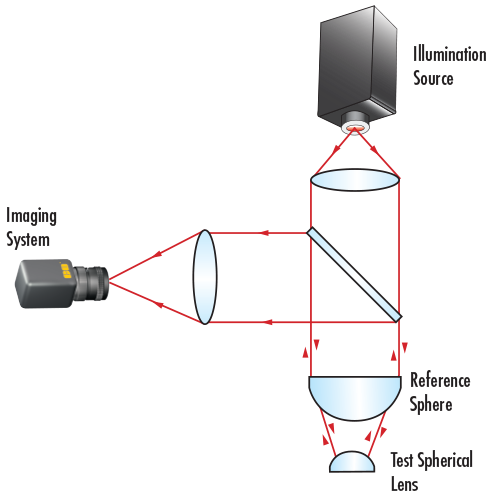
Figure 6: Power error tested by comparing to a reference surface or using an interferometer.
Power error is related to the error in the radius of curvature by the following equation where ∆R is the radius error, D is the lens diameter, R is the surface radius, and λ is the wavelength (typically 632.8nm):
Irregularity
Irregularity, a type of surface accuracy specification, describes how the shape of a surface deviates from the shape of a reference surface. It is obtained from the same measurement as power. Regularity refers to the sphericity of the circular fringes that are formed from the comparison of the test surface to the reference surface. When the power of a surface is more than 5 fringes, it is difficult to detect small irregularities of less than 1 fringe. Therefore it is common practice to specify surfaces with a ratio of power to irregularity of approximately 5:1. For more detailed information on optical flats and interpreting fringe patterns to test surface flatness, power and irregularity, view Optical Flats.
Surface Finish
Surface finish, also known as surface roughness, measures small scale irregularities on a surface. They are usually an unfortunate by-product of the polishing process. Rough surfaces tend to wear faster than smooth surfaces and may not be suitable for some applications, especially those with lasers or intense heat, due to possible nucleation sites that can appear in small cracks or imperfections. Manufacturing tolerances for surface finish range from 50Å RMS for typical quality, 20Å RMS for precision quality, and 5Å RMS for high quality.
MATERIAL SPECIFICATIONS
Index of Refraction
The index of refraction of a medium is the ratio of the speed of light in vacuum to the speed of light in the medium. Typical indices of refraction for glass range from 1.4 - 4.0; visible glasses have lower ranges than those optimized for the infrared. For example, N-BK7 (a popular visible glass) has an index of 1.517, whereas, germanium (a popular IR glass) has an index of 4.003. For more information on infrared materials, view The Correct Material for Infrared (IR) Applications. The index of refraction of an optical glass is an important property because the power of an optical surface is derived from both the radius of curvature of the surface and the difference in the index of refraction of the media on either side of the surface. Inhomogeneity, specified by the glass manufacturer, describes the variation of index of refraction in a glass. It is specified according to different classes, where class and inhomogeneity are inversely related – as class increases, inhomogeneity decreases (Table 3).
| Table 3: Inhomogeneity Specifications | |
|---|---|
| Inhomogeneity Class | Maximum Permissible Variation of Index of Refraction |
| 0 | +/- 50 x 10-6 |
| 1 | +/- 20 x 10-6 |
| 2 | +/- 5 x 10⁻⁶ |
| 3 | +/- 2 x 10⁻⁶ |
| 4 | +/- 1 x 10⁻⁶ |
| 5 | +/- 0.5 x 10⁻⁶ |
Abbe Number
Another material property of glasses is the Abbe number, which quantifies the amount of dispersion that a glass exhibits. It is a function of the refractive index of a material at the f (486.1nm), d (587.6nm), and c (656.3nm) wavelengths (Equation 3),
Typical values of Abbe number range from 25 – 65. Glasses with an Abbe number greater than 55 (less dispersive) are considered crown glasses and those with an Abbe number less than 50 (more dispersive) are considered flint glasses. Due to dispersion, the index of refraction of a glass varies with wavelength. The most notable consequence of this is the fact that a system will have slightly different focal lengths for different wavelengths of light. For more detailed information on important material specifications such as index of refraction and Abbe number, please view Optical Glass.
Laser Damage Threshold
Laser damage threshold indicates the maximum amount of laser power per area that a surface can withstand before it is damaged. Values are provided for pulsed lasers and continuous wave (CW) lasers. Laser damage threshold is a very important material specification for mirrors since they are used in conjunction with laser products more than any other optic; however, any laser-grade optic will provide a threshold. For example, consider a Ti: Sapphire Laser Mirror with damage threshold ratings of 0.5 J/cm2 @ 150 femtosecond pulses and 100kW/cm2 CW. This means that the mirror can withstand energy densities of 0.5J per square centimeter from a high repetition femtosecond pulsed laser or 100kW per square centimeter from a high power CW laser. If the laser is concentrated on a smaller region, then the proper consideration must be taken to ensure the overall threshold does not exceed the specified values.
Though a host of additional manufacturing, surface, and material specifications exist, understanding the most common optical specifications can greatly alleviate confusion. Lenses, mirrors, windows, filters, polarizers, prisms, beamsplitters, gratings, and fiber optics share a variety of attributes, therefore, knowledge of how they relate to each other and can affect overall system performance helps to choose the best components for integration into optics, imaging, or photonics applications.


or view regional numbers
QUOTE TOOL
enter stock numbers to begin
Copyright 2023, Edmund Optics Inc., 18 Woodlands Loop #04-00, Singapore 738100
California Consumer Privacy Act (CCPA): Do Not Sell or Share My Personal Information
California Transparency in Supply Chains Act